Parameter table example, Example design avalon controller – Altera PHYLite User Manual
Page 29
Parameter Table Example
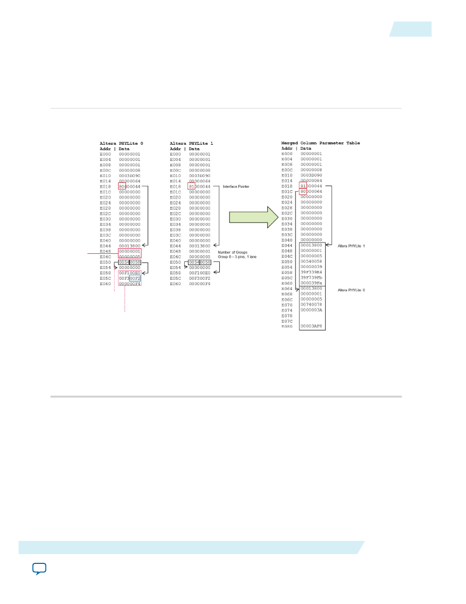
Figure 17: Parameter Table Example
This figure shows an example of a design containing two Altera PHYLite interfaces, each with one
bidirectional group composed of 4 data bits and one strobe. Both interfaces are in the same I/O
column and therefore their tables must be merged.
1 group with 5
pins and 1
lane in the
interface
Pin
Pointer
Lane
Pointer
strobe_io = lane 0x00, pin 0
data_io[0] = lane 0x00, pin 1
data_io[1] = lane 0x00, pin 2
data_io[2] = lane 0x00, pin 3
data_io[3] = lane 0x00, pin 4
strobe_io = lane 0x00, pin 0
data_io[0] = lane 0x00,pin 1
data_io[1] = lane 0x00, pin 2
data_io[2] = lane 0x00, pin 3
data_io[3] = lane 0x00, pin 4
strobe_io = lane 0x39, pin 4
data_io[0] = lane 0x39,pin 3
data_io[1] = lane 0x39, pin
11
data_io[2] = lane 0x39, pin 7
data_io[3] = lane 0x39, pin 10
strobe_io = lane 0x3A, pin 4
data_io[0] = lane 0x3A, pin 1
data_io[1] = lane 0x3A, pin 9
data_io[2] = lane 0x3A, pin 10
data_io[3] = lane 0x3A, pin 8
3AF13AE4
3AFA3AF9
Note: Note there is no guarantee of the ordering of the interface parameter tables in the
merged table, so a specific interface will have to be searched for.
For more information about the contents of the parameter table, refer to
.
Example Design Avalon Controller
An addressing operation can be complicated and error prone. Accidentally addressing the wrong interface
of the IP cores may result in debugging runtime errors difficulties. Therefore, the example design provides
an Avalon controller to simplify the dynamic control of an interface. Altera recommends you to simply
integrate the provided example controller into a dynamic reconfiguration design.
ug_altera_phylite
2015.01.16
Parameter Table Example
29
Altera PHYLite for Parallel Interfaces IP Core User Guide
Altera Corporation