Addressing – Altera PHYLite User Manual
Page 21
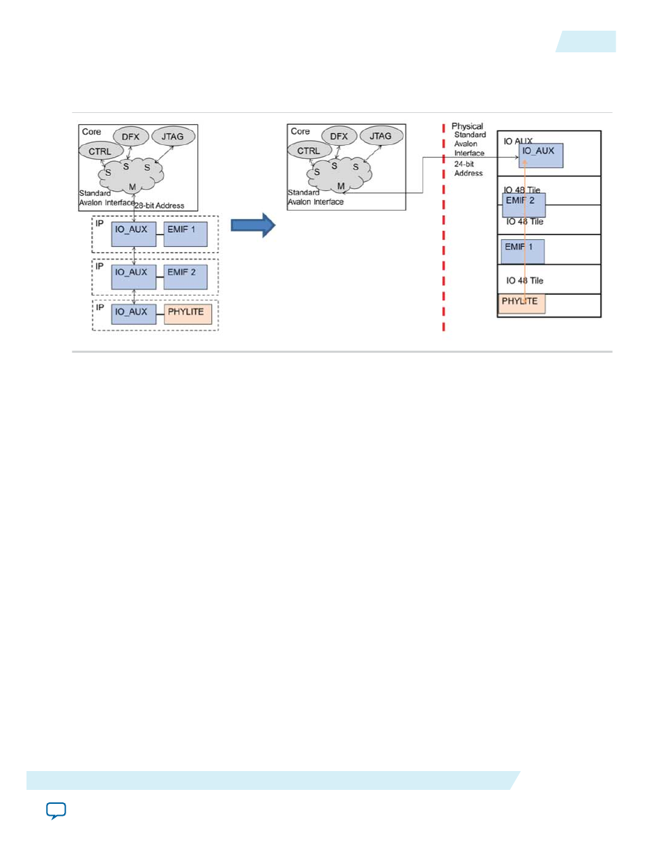
Figure 14: Logical RTL View to Physical Column Placement
This figure shows an example of a daisy chain consisting of the Arria 10 External Memory Interfaces and
Altera PHYLite for Parallel Interfaces IP cores before and after placement.
Notice that all core controllers must go through the arbitration logic that you created in the FPGA core
logic to connect to an interface on the daisy chain. The end of the daisy chain should have its master
output interface tied off.
Note: The prefit netlist of a design using the daisy chain will not simulate correctly due to the rearrange‐
ment of the Avalon address pins, which is done by the Fitter. The postfit netlist will properly
simulate the merged I/O column.
Addressing
Each reconfigurable feature of the interface has an associated memory address. However, this address is
placement dependent so addresses of the interface lanes, as well as the pins must be tracked in order to
use the IP in a column that can be shared with other Altera PHYLite for Parallel Interfaces and the Arria
10 External Memory Interfaces IP cores, which also use the Avalon Bus.
Note: Addressing is done at the 32-bit word boundary; avl_address[1:0] = 00
ug_altera_phylite
2015.01.16
Addressing
21
Altera PHYLite for Parallel Interfaces IP Core User Guide
Altera Corporation