Altera PHYLite User Manual
Page 27
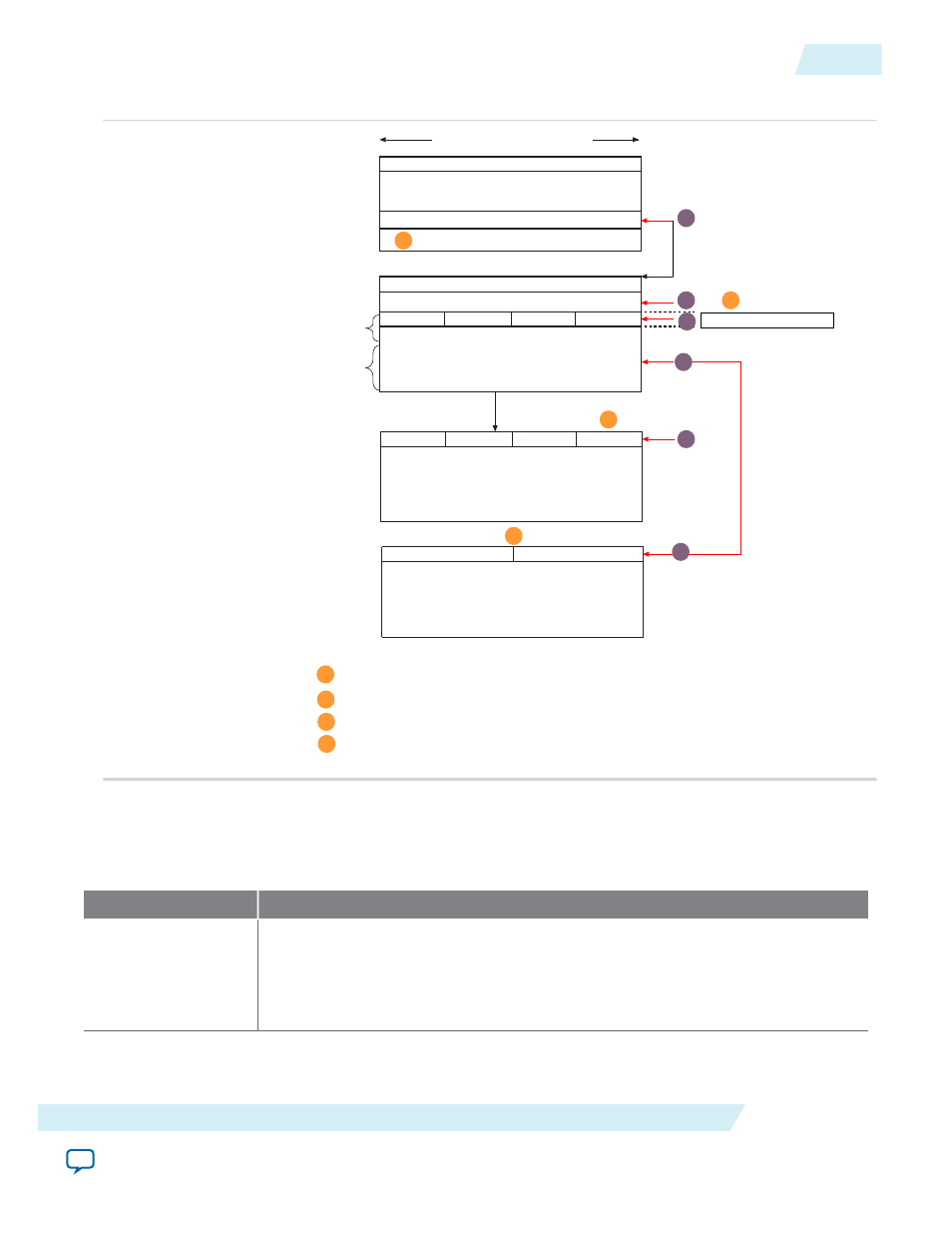
Figure 16: Memory Overview
Group 0 Pin 1
Group 0 Pin 0
num_lanes[1:0],num_pins[5:0]
Needed for pin
address lookups
Needed for simplifying
strobe feature logic
address lookups
One per Interface
num_lanes[1:0] starts counting at 0. For example, 0 = 1 lane, 1 = 2 lanes, 2 = 3 lanes, 3 = 4 lanes
Lane address table information: Group X Lane Y = lane_addr[7:0]
Pin address table information: Group X Pin Y = {lane_addr[7:0],0xF,pin[3:0]} for data and
{lane_addr[7:0],0xE,pin[3:0]} for strobe
B
C
D
D
C
B
Number of Groups
Number of Groups
{id[3:0],24’h00E000} + pt_ptr
{id[3:0],24’h00E000} + pt_ptr 28’d4
Parameter Table
(PHYLite Specific)
{id[3:0],24’h00E000} + pt_ptr +
{22’d0,num_grps[7:2],2’b00} + 28 d8
lane_ptr[15:0],pin_ptr[15:0]
{id[3:0],24’h00E000} + lane_ptr
Lane Address Table
(PHYLite Specific)
Group 0 Lane 0
{id[3:0],24’h00E000} + pin_ptr
Pin Address Table
(PHYLite Specific)
32-bits (4 Byte Addresses)
{id[3:0],24’h00E000}
Global Parameter Table
(One per column, same as EMIF)
{id[3:0],24'00E018}
{4’b1000,id[3:0], pt_ptr[23:0]
PT_VER[15:0],IP_VER[15:0]
Number of Groups
{4'h8,id[3:0],8'h00,interface_table_ptr[15:0]}
A
The MSB of the interface pointer entry in the global parameter table is 1 for PHYLite interfaces.
A
1
2
3
4
5
6
The Parameter table look-ups are used as follows (the sequence corresponds to the sequence in
):
Table 14: Parameter Table Lookup Operation Sequence
Description
1
Search for Interface Parameter Table in Global Parameter Table (cache once per
interface)
• {id{3:0],24'h00E000} + 28'h18 to {id{3:0],24'h00E0000} + 28'h2C
• 1 to 11 look-ups
ug_altera_phylite
2015.01.16
Address Look-Up
27
Altera PHYLite for Parallel Interfaces IP Core User Guide
Altera Corporation