LINK Systems OmniLink II Press Automation Control User Manual
Page 91
August 30, 2002 Manual Version 1.0
5.8
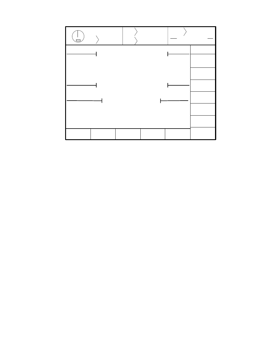
Figure 5.4 Diagnostics Screen
The softkeys along the bottom of the screen navigate to other screens where high speed serial
communication, memory, and software version information diagnostics are shown. This raw information
is only useful for user diagnostics in the field as an aid in diagnosing possible problems over the phone
with Link technicians. The phone service technician will direct you to these screens if necessary.
The EVENT LOG softkey is used to access the Event Log screen, which stores the last 128 Reason for
the Last Stop messages with a date and time (the OmniLink incorporates a battery operated clock)
stamp.
Section 5.2.9 Module Limit Switch
The R/D-Brake Monitor provides the logic for two simple programmable limit switch outputs as
standard. Since these outputs can only sink 8ma of dc current, enough to operate solid state ac or dc
relays, optional solid state relays must be provided to make these two Module PLS channels practical for
driving larger loads. Link provides an optional 802-5 Solid State Relay Module (shown in Figure 2.18)
that can provide up to 4 solid state relays, 2 for Module PLS channels 1 and 2, and 2 for optional
indicator functions that may be driven by the R/D-Brake Monitor Module.
The Module Limit Switch screen can always be accessed by pressing the MODULE LIMIT SWITCH
softkey on the Brake Monitor screen. If no optional PLS/Logic Module is used with the system, the
LIMIT SWITCH softkey on the Main Menu will also access the Module Limit Switch screen. If one or
more PLS/Logic Modules is used with the system, the LIMIT SWITCH softkey on the Main Menu will
access the PLS/Logic Module screens, and only the MODULE LIMIT SWITCH softkey on the Brake
Monitor screen will access the Module Limit Switch screen.
The Module Limit Switch screen simply shows the two channel numbers and the ON and OFF angles
for each. You can view the information in Run mode and make settings in Program mode.
Stroke
Mode
Drive
Speed
Stroke
Speed
SPM
SPM
0
0
Order
Counter
SYSTEM STATUS
Counter OFF
Diagnostic
0
0
OK
TOP
EXIT
EVENT
LOG
H. S. COMM
DIAGS
KEYBOARD
TEST
S. MEDIA
INFO
VERSION
INFO
R2D/Brake Monitor Module CON2 States
PLS 1 (CON2, Pin 2): On
PLS 2 (CON2, Pin 3): Off
Out 3 (CON2, Pin 4): Off
Out 4 (CON2, Pin 5): Off
In 1 (CON2, Pin 6): Off
Setup/Prod Mode Input (CON2, Pin 6): On
R2D/Brake Monitor Module Stop Relays
Stop Relay 1 (Left): On
Stop Relay 2 (Right): On
R2D/Brake Monitor Module Other
Raw R2D: 007C
Raw Speed Input: 0000
Raw Speed Output:0000
Raw Motor Load Input: 0000