LINK Systems OmniLink II Press Automation Control User Manual
Page 115
August 30, 2002 Manual Version 1.0
6.10
V+
SIGNAL
COM
V+
SIGNAL
COM
24 VDC
0 VDC
TO INPUT
NPN CONNECTIONS
V+
SIGNAL
COM
V+
SIGNAL
COM
24 VDC
0 VDC
TO INPUT
SERIES
PARALLEL
PNP CONNECTIONS
24 VDC
0 VDC
TO INPUT
SERIES
V+
SIGNAL
COM
V+
SIGNAL
COM
24 VDC
0 VDC
TO INPUT
PARALLEL
V+
SIGNAL
COM
V+
SIGNAL
COM
V+
SIGNAL
COM
24 VDC
0 VDC
TO INPUT
SINGLE
TO INPUT
24 VDC
0 VDC
SINGLE
V+
SIGNAL
COM
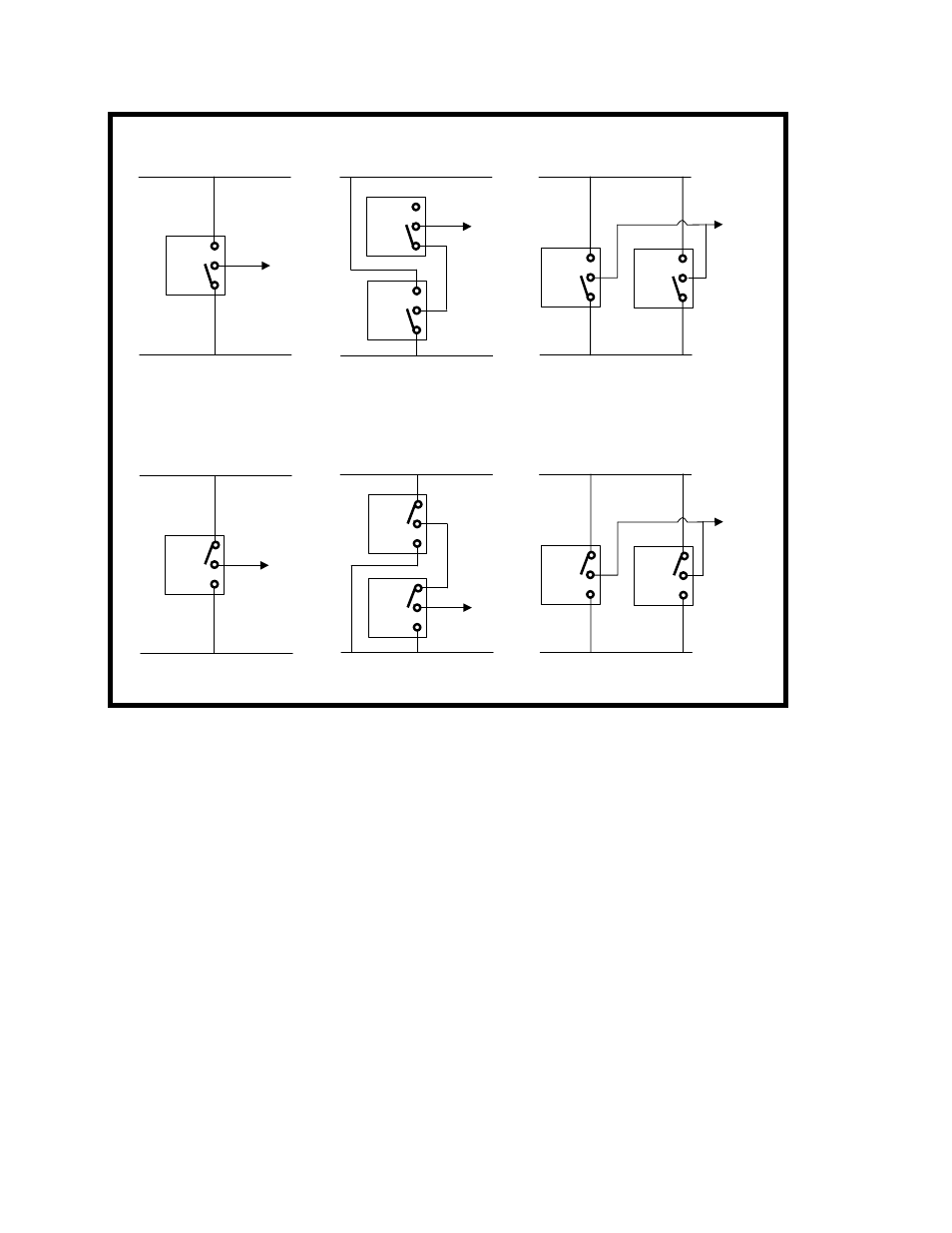
Figure 6.4 Solid State Sensors Single, Series, and Parallel Connections
Section 6.5 Die Protection Input Types and Their Uses
Each die protection channel can be programmed for any one of nine different die protection types:
Static, Cyclic, Transfer, In Position, 1 Part Detection Edge, 1 Part Pass, 2 Part Detection Edge, 2 Part
Detection Pass, and Custom. In addition, any input can be set to Not Used if desired.
Sensor logic is assigned descriptive names such as Static, Cyclic, and 1 Part Pass. Although these
names best describe the applications for which they are normally used, their use should not be limited by
their assigned name. For example, if a channel requires the logic of a 1 Part Pass and the sensor is not
actually detecting a part out, 1 Part Pass logic should still be used. Each channel can have its own
description. Although the 1 Part Pass logic is employed, the assigned description can indicate the
precise use of the channel.
Section 6.5.1 Static
Static inputs are used for sensors that monitor events that are independent of the production machine
cycle. Examples are sensors monitoring end of stock and stock buckling. If the input is programmed as