Figure 7.7 die protection setting screen – LINK Systems OmniLink II Press Automation Control User Manual
Page 151
August 30, 2002 Manual Version 1.0
7.14
Section 7.7.1 Channel Settings
The channel settings define the mode of the channel and the parameters associated with the mode. The
Limit Switch screen is shown in Figure 7.6. The screen displays channel mode, description, status, and
state for eight limit switch channels. Additional information specific for one channel, channel 1 in
Figure 7.6, is displayed in the bottom section of the screen. The additional information includes the
channel on and off setpoints and a graphical display of the settings. The information on the Limit
Switch screen is view only information. Channel setting cannot be changed on this screen.
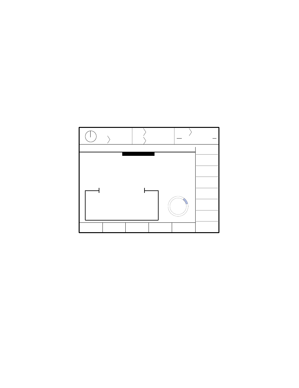
In order to change channel settings, the CHANNEL SETTINGS softkey must be selected. The PLS
Change Settings screen will be displayed. This screen is shown in Figure 7.7.
The channel settings can by changed by a user who has gained access control. See Section 3.9 for
information concerning access control. There are several items that can be programmed on this screen.
The item list changes depending on the type of channel mode that is selected. In Figure 7.7 a Normal
channel type is selected. The remaining items are all associated with Normal mode PLS. In addition,
the help screens are specific for the highlighted parameter. The following sections contain a description
of all possible items that may appear on the Limit Switch Setting screen. Some of these items will not
appear on all screens, because they do not apply to the selected channel type.
Section 7.7.1.1 Channel Modes
The channel mode can be selected from the following listing.
Stroke
Mode
Drive
Speed
Stroke
Speed
SPM
SPM
0
0
Order
Counter
SYSTEM STATUS
Counter OFF
PLS Chan
Settings
CHANGE
SETTING
EXIT
0
0
Program/Run Switch
TOP
Production
NEXT
CHANNEL
INCREASE
OFF ANGLE
PREVIOUS
CHANNEL
DECREASE
OFF ANGLE
INCREASE
ON ANGLE
DECREASE
ON ANGLE
PLS Channel 5 Settings
Channel Mode:
Description:
Speed Adjust:
Counted Outputs:
On Angle:
Off Angle:
Counted Out. Limit:
Counted Out. Count:
Spd. Adv. Lead Time:
Spd. Adv. Trail Time:
270
0
180
90
Normal
Die Spray Lube
Both Edges
By Stroke
45°
75°
5
4
75 msecs.
55 msec.
Help
Sets the mode of the channel.
Figure 7.7 Die Protection Setting Screen