Inside of operator terminal enclosure, 5 r/d-brake monitor module, Con8 – LINK Systems OmniLink II Press Automation Control User Manual
Page 28
August 30, 2002 Manual Version 1.0
2.19
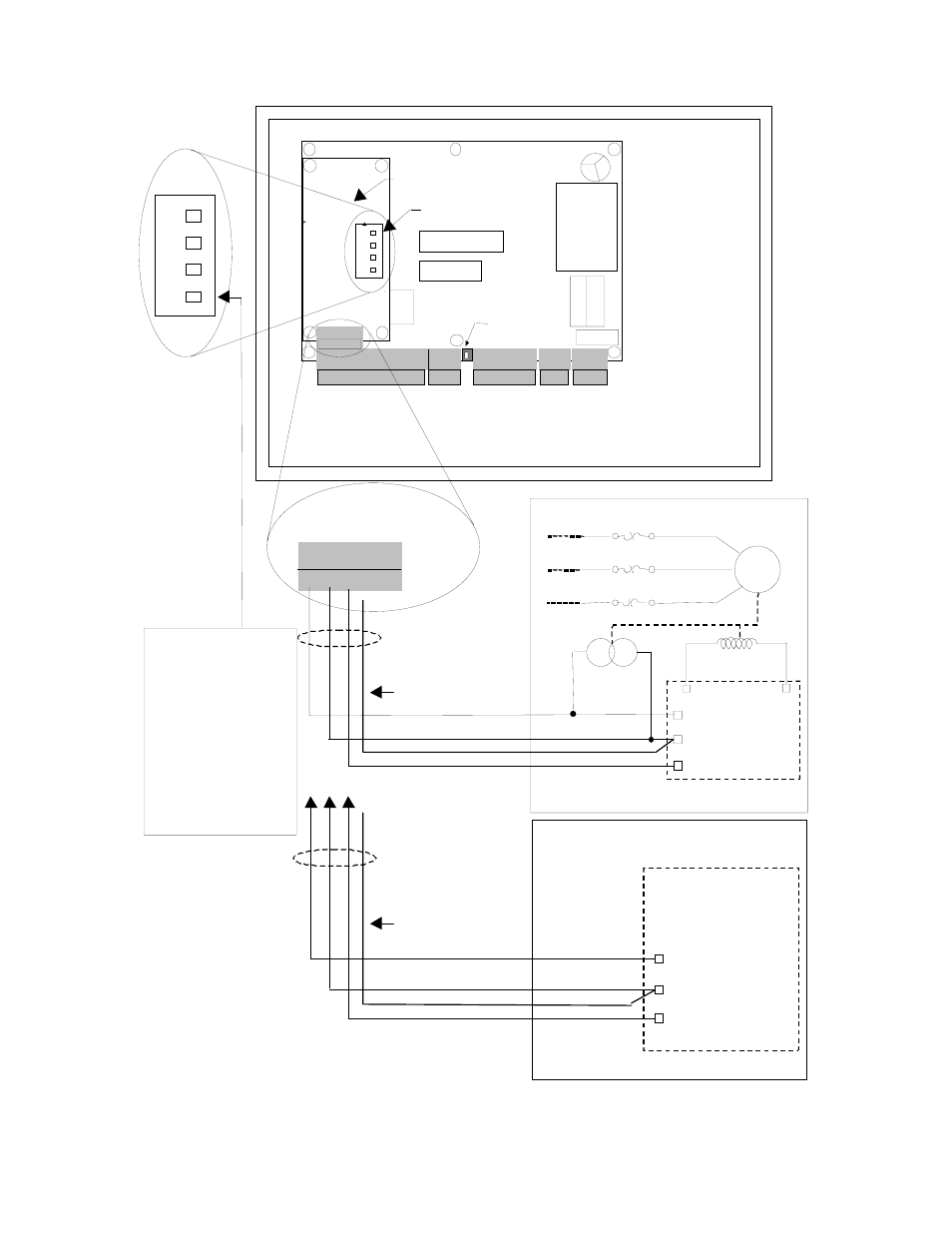
Figure 2.17 Wiring to Display and Set SPM Through OmniLink II Operator Terminal
EDDY CURRENT
COUPLING CO IL
DC MOTOR DRIVE OR
AC ADJUSTABLE
FREQUENCY DRIVE
PRESS CONTROL
DRIVE GROUND
ANALOG 0-10V SPM OUTPUT
FOR DC MOT OR DRIVE OR AC ADJUSTABLE
FREQUENCY DR IVE VARIABLE SPEED PRESSES
Transformer
Fuse
Output
Relays
Microprocessor 1
Microproc. 1
Prog. Memory
R1 2 3 4 5 6 7 8 9 10 11 12 13
CON7
SH
LD
GN
D
CA
NH
CA
NL
Can Termination
Switch
CON1
CON2
1 2 3
4 5 6 7 8 L1 L2 GND
CON5
1 2 3 4
CON4
1 2 3 4 5
CON8
R/D
IC
Analog Input/Output
802-5 R/D-Brake Monitor Module
INSIDE OF
OPERATOR
TERMINAL
ENCLOSURE
1 2 3 4 5
CON8
SP
M
IN
IS
O
G
N
D
IS
O
G
N
D
SP
M
O
U
T
%L
O
A
D
1M
MAIN MOTOR
1OL
1OL
1OL
PRESS CONTROL
FOR EDDY CURRENT DRIVE PRESSES
2
1
12
3
4
12
3
4
SWITCH
Board Option
OP
E
N
Throw switch 1 to
closed position if eddy
current tach generator
is referenced to ground
on eddy current drive &
for DC or AC motor
drives with analog voltage
speed outputs. Switch to
open position for eddy
current tach generator
that is input to a bridge
rectifier (rarely the case)
on the eddy current drive.
EDDY CURRENT DRIVE
DRIVE GROUND
DRIVE SPM FEEDBACK
ISOLATED
INPUTS &
OUTPUT
DRIVE SPM INPUT
DRIVE SPM INPUT
3
TACH
GENERATOR
SHIELDED CABLE
IN LOW VOLTAGE
CONDUIT
SHIELD
No Connection
No Connection
SHIELD
SHIELDED CABLE
IN LOW VOLTAGE
CONDUIT