LINK Systems OmniLink II Press Automation Control User Manual
Page 31
August 30, 2002 Manual Version 1.0
2.22
Section 2.4.2 Wiring the Base Components in the Customer Enclosure
The only wiring not shown in previous figures where base system components were supplied in an
enclosure is the wiring between R/D-Brake Monitor Module and Operator Terminal. You will be
supplied a 5’ length of high speed serial bus cable that may be cut to the actual required length. Connect
one end of the cable to the bottom row of terminals on the dual plug for Connector 5 on the R/D-Brake
Monitor Module and the other end to the lower left connector on the back of the operator terminal.
Connect as follows on both connectors.
Cable Wire Color
Connector Terminal
White
CANL
Orange
CANH
Blue
GND
Bare
Shield
Run individual red, white, and green wires between the power connector (CONN 5) on the R/D-Brake
Monitor and the power connector at the upper left of the back of the operator terminal. Connect red to
L1 on both connectors, white to L2 on both connectors and green to GND on both connectors. If the 4-
channel Output Relay Module is supplied, wire from R/D-Brake Monitor Module to Output relay
module as shown in Figure 2.18.
Section 2.5 Wiring Serial Ports for Serial Feed Interface, PLC Interface, and
LinkNet Information System Options
Wiring for serial feed interface, PLC Interface, and LinkNet Information System options will be outlined
R 1 2 3 4 5 6 7 8 9 1 0 1 1 1 2 1 3
CON 7
CON 1
4
3
CON 2
5 6 7 8
2
1
1
CON 4
3
2
4
CON 5
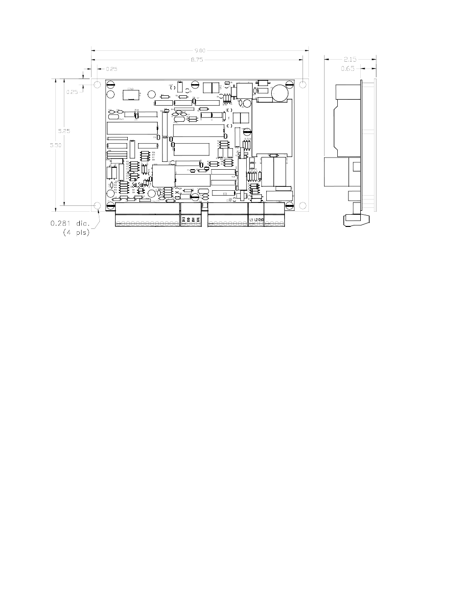
Figure 2.20 R/D-Brake-Monitor Module with Mounting Bracket for Mounting in
Customer’s Enclosure