Two part-pass, Figure 6.17 one part detector pass, Figure 6.18 one part detector pass timing – LINK Systems OmniLink II Press Automation Control User Manual
Page 124: Separation time
August 30, 2002 Manual Version 1.0
6.19
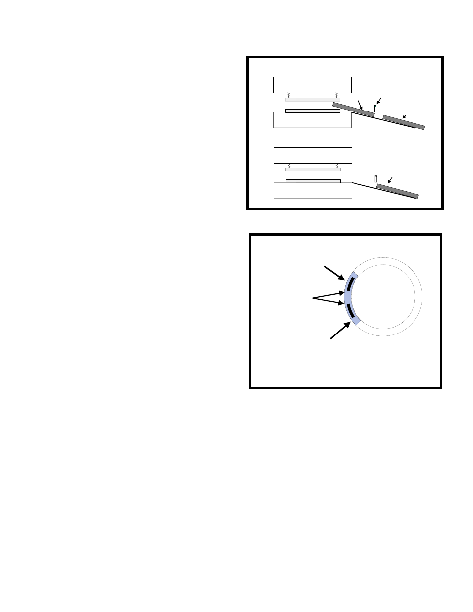
The Two Part Detector Pass input type timing
requires that the input sensor detect both parts
during the timing window only. The sensor
cannot detect the presence of a part at the
beginning or at the end of the timing window,
but it must detect the presence of the parts
during the timing window. In other words, the
Part Detector Pass type requires that the sensor
NOT be active when the window turns ON,
sense two parts during the window, and not be
active at the end of the window. There must be
a separation time between the parts. The first
part must completely exit the sensor before the
second part enters the sensor. The timing for
Two Part Detector Edge is shown in Figure 6.18.
Note the input is programmed as ‘Two Part
Detector Pass’, the sensor is not allowed to
become active outside the window or a fault
will be generated. This provides protection
against a part ‘bouncing’ on a probe-type
detector and satisfying the die protection input
erroneously.
The sensor being used to verify part detection
can be Normally Off or Normally On. The
sensor will switch from its normal state when the
part is being detected. When a Normally Off
sensor is being used to sense part out; the sensor
will be Off when the part is not in the sensor,
and will be On when the part is in the sensor.
When a Normally On sensor is being used to
sense part out; the sensor will be On when the
part is not in the sensor, and will be Off when
the part is in the sensor.
Section 6.5.8 Transfer
Transfer type inputs are used to monitor automatic transfer mechanisms. Some progressive dies cut the
part away from the stock at an early stage in the die. Automatic transfer mechanisms are then used to
move the separate pieces to the next stage in the die. Each gripper on the transfer mechanism should
have a sensor to detect that each part is in place in the transfer mechanism. These switches can be wired
to channel inputs programmed as Transfer type to monitor the mechanism for dropped parts during the
transfer.
When programming a channel for transfer type, the operator must enter crankshaft angles to mark On
and Off points for a timing 'window' during which the transfer will occur. The Window On setpoint
should be set to an angle just after the part is gripped. The window Off setpoint should be set to an
UPPER DIE
LOWER DIE
SECOND PART
SENSOR
UPPER DIE
LOWER DIE
SECOND PART
WHEN THE LEADING EDGE OF THE SECONT PART
IS FIRST DETECTED,ITS TRAILING EDGE
IS STILL IN THE DIE AREA
THE SECOND PART IS COMPLETELY OUT OF
THE DIE AREA WHEN IT PASSES THE SENSOR
FIRST PART
Figure 6.17 One Part Detector Pass
0
180
90
Second Part Must
Exit In Timing
Window
First Part Must
Enter In Timing
Window
Two Part-Pass
Separation
Time
Figure 6.18 One Part Detector Pass Timing