Figure 7.4 programmable limit screen – LINK Systems OmniLink II Press Automation Control User Manual
Page 148
August 30, 2002 Manual Version 1.0
7.11
The Programmable Limit Switch system should be configured before being put into operation. This
configuration allows the user to select the manner that the system can be reset and the use of speed
advanced outputs. The user is encouraged to look at all possible configuration options, and then choose
the options that best fit his applications.
To enter the Configuration screen, place the Run/Program key switch in the Program position, then
select the CONFIGURE softkey. A popup box which requests that the user enter the user configuration
code, highest order user password. After entry of the correct code, the Die Protection System
Configuration screen will appear. This screen is shown in Figure 7.5.
Stroke
Mode
Drive
Speed
Stroke
Speed
SPM
SPM
0
0
Order
Counter
SYSTEM STATUS
Counter OFF
Limit
Switch
CHANGE
CHANNEL
SETTING
EXIT
0
0
Program/Run Switch
TOP
Production
NEXT
PAGE
180
0
270
90
Ch Mode
Description
Status
State
CONFIGURE
RESET
FAULT
1
2
3
4
5
6
7
8
Normal
Timed Off
Toggle
Normal
Normal
Always Off
Always Off
Always Off
Feed Initiate
Air Blow Off
Parts Bin Select
Pilot Pin Release
Die Spray Lube
OK
OK
OK
OK
OK
OK
OK
OK
On
Off
Off
Off
Off
Off
Off
Off
Channel 1 Details
System Status: OK
Module Status: OK
Channel
Status
Ok
On Angle:
Off Angle:
270°
10°
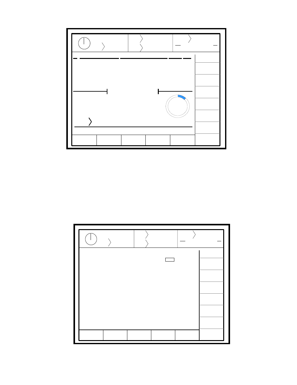
Figure 7.4 Programmable Limit Screen
Stroke
Mode
Drive
Speed
Stroke
Speed
SPM
SPM
0
0
Order
Counter
SYSTEM STATUS
Counter OFF
PLS
Sys. Cfg.
CHANGE
SETTING
EXIT
0
0
Program/Run Switch
TOP
Production
RESTRICT
UNRESTRICT
Reset Resets All Channels:
Allow Speed Adjusted Outputs:
No
Yes
Figure 7.5 Programmable Limit Switch Configuration Screen