Con5, Con4, L1 l2 gnd – LINK Systems OmniLink II Press Automation Control User Manual
Page 22: Press control, Motor controls, Clutch/brake dual air valve, Clutch/brake control
August 30, 2002 Manual Version 1.0
2.13
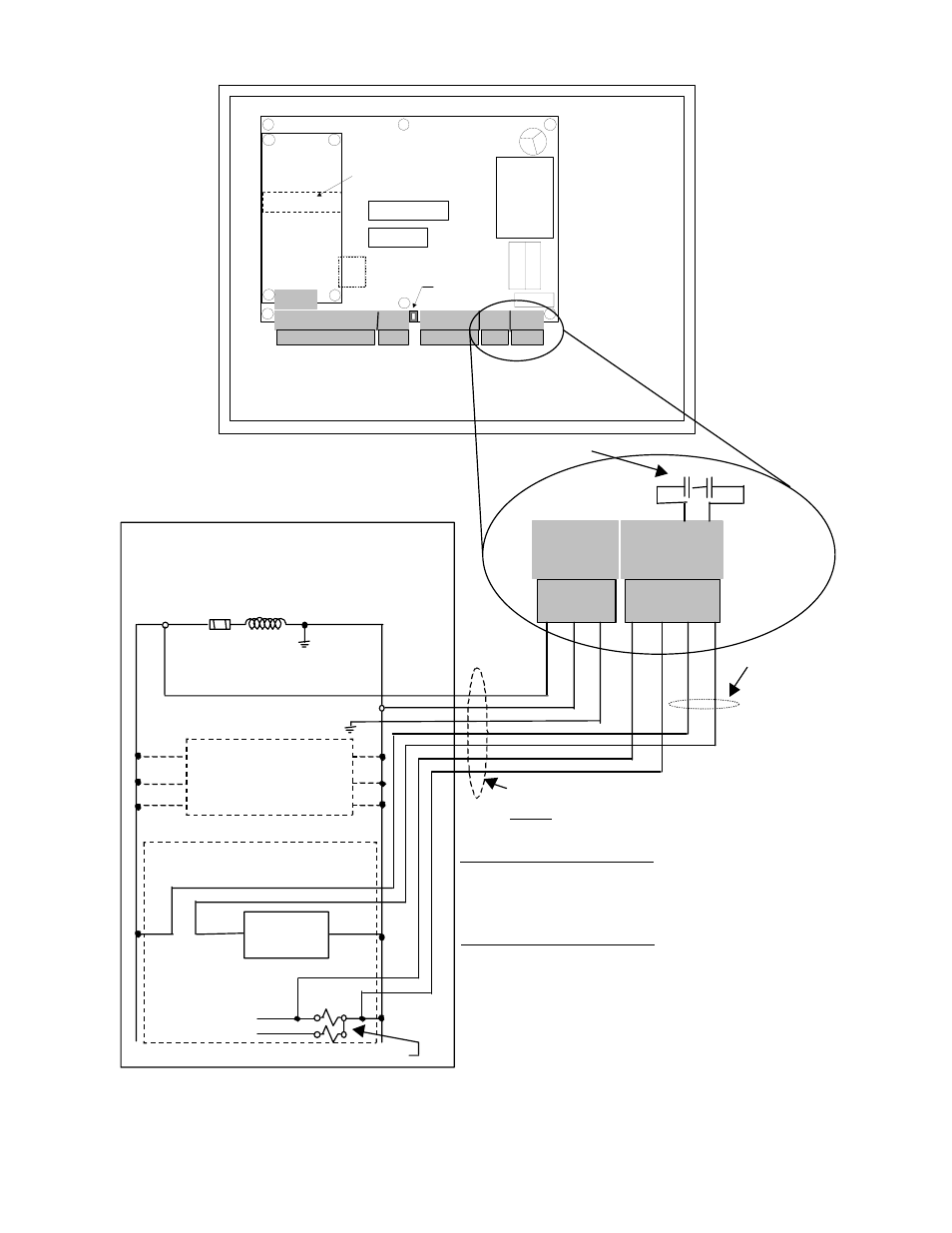
Figure 2.13 115VAC Wiring Between Press Control and Operator Terminal
L1 L2 GND
CON5
1 2 3 4
CON4
CR1 CR2
FUSE
Transformer
Fuse
Output
Relays
Microprocessor 2
Microprocessor 1
Microproc. 1
P rog. Memory
R 1 2 3 4 5 6 7 8 9 1 0 1 1 12 1 3
CON7
SH
LD
GN
D
CA
NH
CA
NL
Can Term ination
Switch
CON1
CON2
1 2 3 4 5 6 7 8
L1 L2 G ND
CON5
1 2 3 4
CON4
1 2 3 4 5
CON8
R/D
IC
Analog Input/Output
Board Option
802-5 R/D-Brake Monitor Module
PRESS CONTROL
115VAC CONTROL TRANSFORMER
SECONDARY WINDING
MOTOR
CONTROLS
CLUTCH/BRAKE
CONTROL
IMME DIATE
CLUTCH STOP
CIRCUIT
115VAC
WH IT E
BLACK
GREEN
RED
RED
RED
RED
1/2” CONDUIT CONTAINING
ONLY 115VAC CONNECTION
CIRCUITS
Contacts on R/D- Brake Monitor Module used to provide both immediate stop
and top stop signals from OmniLink to press control. These contacts open
immediately when an immediate stop is required and are delayed in opening
as appropriate to stop the press on top when top stop is required.
CONNECTOR 5 TERMINALS
L1,L2,GND - 115VAC Power for OmniLink
Press Automation Control from
press control transformer.
CONNECTOR 4 TERMINALS
1,2 ---
Wire to Press Control Dual Valve
solenoid. Tells OmniLink when
press strokes or stops for Brake
Monitor & Motion Detector.
3,4---
Wire into immediate clutch
(stroking) stop circuit. Provides
both immediate and top stop.
INSIDE OF OPERATOR TERMINAL ENCLOSURE
Note! If press
control clutch
stop circuit is
low voltage
instead of 115V,
run these wires
in conduit for
low voltage
connections.
CLUTCH/BRAKE DUAL AIR VALVE