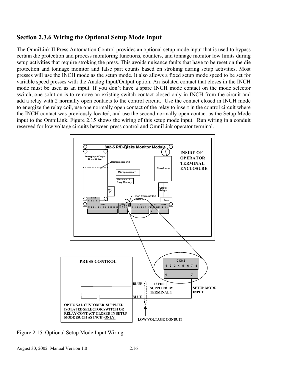
Figure 2.15. optional setup mode input wiring, Inside of operator terminal enclosure, Press control – LINK Systems OmniLink II Press Automation Control User Manual
Figure 2.15. optional setup mode input wiring, Inside of operator terminal enclosure, Press control | 5 r/d-brake monitor module | LINK Systems OmniLink II Press Automation Control User Manual | Page 25 / 154
See also other documents in the category LINK Systems Measuring instruments: