Echelon LonPoint Application and Plug-In User Manual
Page 64
6-8
Analog Input Functional Block
current setting is determined by two factors: absolute range and self-heating
limitations.
The absolute range refers to the upper input voltage limit of the A/D converter
after voltage input scaling: 2.500VDC (scaling allows measurement of voltages
higher than this limit). Any voltage higher than this limit will not be
measurable. The maximum resistance that can be measured at 25µA is
2.5V/25e-6A = 100k
Ω
, and at 400µA is 2.5V/400e-6A = 6.25k
Ω
. Resistances
higher than 100k
Ω
at 25µA, or 6.25k
Ω
at 400µA, will not damage the LonPoint
module but they will not be measurable.
Self-heating is another consideration that may merit the use of the lower 25µA
current setting, even if the absolute limit is not a factor. Heat is generated
whenever a current is passed through a resistor, but when you’re trying to
measure temperature this heat generation affects the accuracy of the reading.
How much the accuracy is affected depends on the current, the thermal mass of
the input, airflow, and so on.
The amount of self-heating power can be calculated by squaring the current and
multiplying by the resistance. For example, a 2k
Ω
thermistor would have
1.25µW of dissipation at the 25µA setting (25µA x 25µA x 2000
Ω
), and 320µW of
self-heating energy dissipation at the 400µA current setting (400µA x 400µA x
2000
Ω
). The error resulting from heat-dissipation depends on the dissipation
constant of the sensor. For example, Kele PreCon thermistors have a dissipation
constant of 2.7mW/°C in still air at room temperature. To calculate the
measurement error, the power dissipation is divided by the dissipation constant,
as follows:
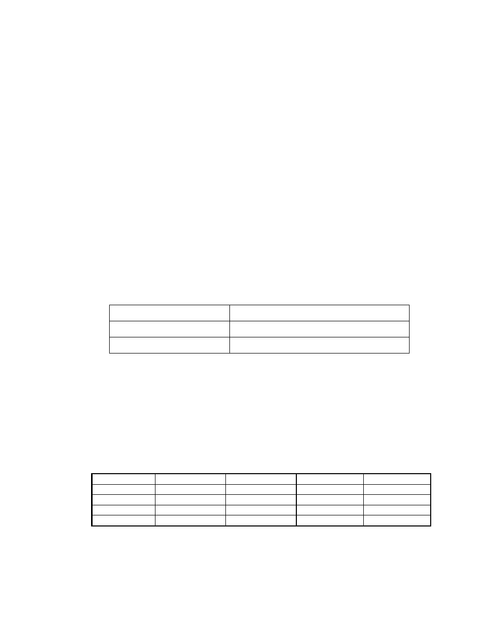
Current
Measurement Error
25µA
1.25µAW/2700µW/dC = 0.0005°C (0.0008°F)
400µA
320µAW/2700µW/dC = 0.12°C (0.22°F)
Depending on the system, these self-heating errors may be small or large
compared to the accuracy of most thermistors; however, they should be taken
into consideration when selecting a current setting.
RTDs have a larger thermal mass, larger dissipation area, and low initial
resistance, and are therefore not as susceptible as thermistors to significant self-
heating errors.
Once the measurement current has been set, the gain should be adjusted to the
maximum value that doesn’t generate over-range errors. The resistor ranges for
the various settings are shown in this table:
AI-10 Analog Input Module RES Settings
Gain Setting
Range @ 400µA
Ω
/step @ 400µA
Range @ 25µA
Ω
/step @ 25µA
x1
0 - 6.25k
Ω
0.0953
0 - 88k
Ω
1.525
x2
0 - 3.12k
Ω
0.0477
0 - 50k
Ω
0.763
x32
0 - 195
Ω
0.00298
0 - 3.12k
Ω
0.048
x128
0 - 49
Ω
0.000745
0 - 781
Ω
0.0119