State transition definitions – Echelon LonPoint Application and Plug-In User Manual
Page 119
The LonPoint Application and Plug-in Guide
10-17
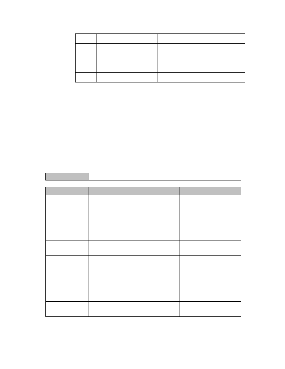
6
HVAC_OFF
Controller not controlling outputs
7
HVAC_TEST
Equipment being tested
8
HVAC_EMERG_HEAT
Emergency heat mode (heat pump)
9
HFAC_FAN_ONLY
Air not conditioned, fan turned on
255
HVAC_NUL
Value not available
4. Click the corresponding entry in the Digital Output Values column and type
the names of all the digital output network variables that should be on after
this transition. The digital outputs are all SNVT_switch values, and you will
specify each as either On or Off.
When you are finished defining a State Definition shape, close the State
Definitions shape drawing window.
Following is an example State Definitions shape. This shape defines the state
transitions for the stUnoccupied state of the example described in Drawing a
State Machine Bubble Diagram earlier in this chapter.
stUnoccupied
cndOccupied
stOccupied
HVAC_AUTO
oOccupied On
oSystemEnable On
cndStartWarmup
stWarmup
HVAC_MRNG_WRMUP
oOccupied On
oSystemEnable On
cndEmergency
stEmergency
HVAC_EMERG_HEAT
oSystemEnable On
cndSystemOff
stOff
HVAC_OFF
Exit Condition
Next State
State Transition Definitions
Mode_Out Value
State Name:
1. Use an additional Transition Definitions shape for each State.
2. Use up to 4 Transition Definitions shapes per state.
Digital Output Values