Top Flite TOPA0110 User Manual
Page 54
4. Paint the interior of the cockpit. An
alternative to paint is to cover the inside of the
cockpit with fine-grit black sandpaper for a
t e x t u r e d f i n i s h . I f y o u u s e t h e s a n d p a p e r
technique, it is still advisable to paint the cockpit
corners black first.
5. Paint the frame of the canopy. This can be
done from the inside or the outside. The choice is
yours. The prototype was painted on the outside,
since the glue seems to stick better if the inside is
unpainted and roughened with sandpaper.
6. Install the instrument panel decal. It may
be applied directly to the existing panel. Hint:
For best results, stick the decal to a scrap piece
of 1/64" to 1/16" plywood, trim it to shape, then
glue it in place.
7. Cut out and glue the canopy to the model.
A “Lexan
®
scissors,” available from your hobby
store, works great for this. We recommend using
RC-56 glue or 5-minute epoxy, but if you have a
favorite technique, use it. You should remove a
small strip of MonoKote from under the frame for
good glue adhesion. Use masking tape to hold
the canopy in place while the glue sets.
INSTALL RECEIVER, SWITCH AND
BATTERY
1.
Wrap your receiver and battery in plastic
bags. Then wrap with foam rubber.
2.
Install the battery and receiver in the
fuselage. NOTE: The receiver was put through
the lightening hole in the crutch between formers
F-3 and F-4. The battery can be seen in the photo
in the aft portion of the wing saddle area against
F-8. The position of the battery and receiver may
be changed to balance the aircraft.
3.
Route the receiver antenna in one of the
following ways:
a.
Route the antenna along the inside of the
fuse side and out of the fuse top, just behind the
canopy. Anchor the antenna to the top of the fin
with a rubber band.
b.
Insert the antenna into a “pushrod guide
tube” (not included) and tape it securely at the aft
end. Install the tube and antenna into the aft
portion of the fuselage through the lightening
holes in the fuselage formers. The entire length
of the antenna should be extended relatively
straight.
BALANCE YOUR MODEL
NOTE: This section is VERY important
and must not be omitted!
A model that is not properly balanced
will be unstable and possibly
unflyable.
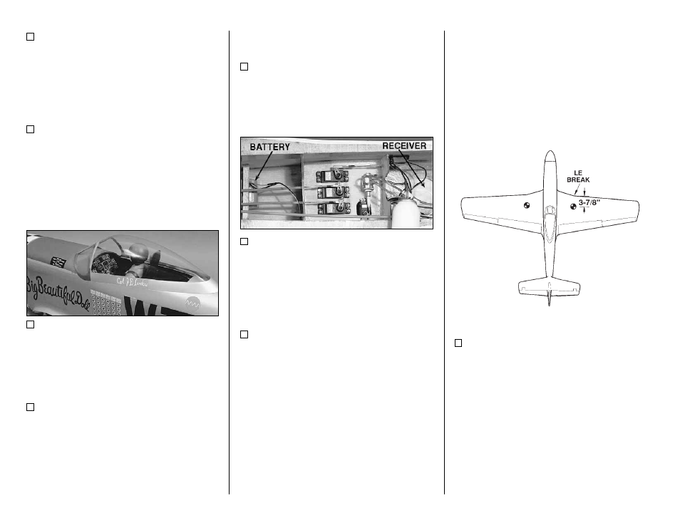
1. Accurately mark the balance point on the
top of the wing on both sides of the fairing. The
balance point is shown on the plan (CG), and is
located approximately 3-7/8" back from the
leading edge at the “LE break” as shown in the
sketch and on the plans. This is the balance
point at which your model should balance for your
first flights. Later, you may wish to experiment by
shifting the balance up to 1/4" forward or back
to change the flying characteristics. Moving the
balance forward may improve the smoothness
and arrow-like tracking, but it may then require
more speed for takeoff and make it more difficult
to slow down for landing. Moving the balance aft
makes the model more agile with a lighter and
- 54 -