Top Flite TOPA0110 User Manual
Page 52
FINAL CONTROL HARDWARE
HOOKUP
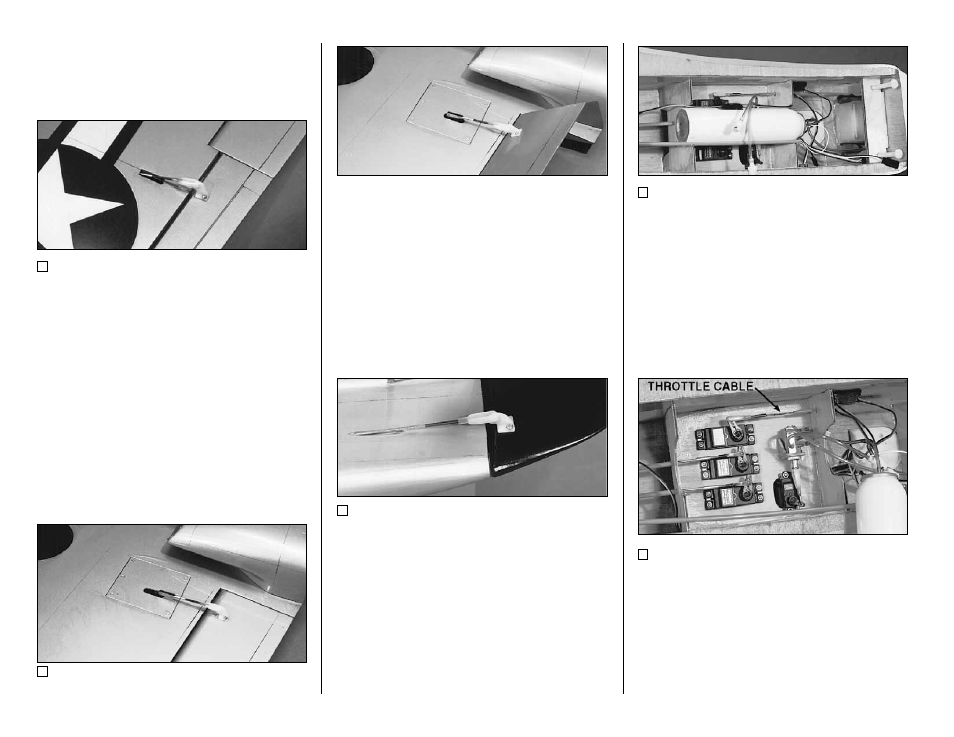
1. Install the flap and aileron horns in line
with the pushrod exits as shown on the plans. On
the prototypes, 1/16" holes were drilled in the
flaps and ailerons at the horn locations. These
holes were then thoroughly soaked with thin CA
glue. The horns were then glued and screwed in
place with #2 x 3/8" Sheet Metal Screws. If
your balsa appears very soft, it is recommended
that you cut a piece of the surface away and
install a 1/8" plywood plate into the surface to
thread the screws into.
2. Hook up and adjust the aileron and flap
linkages. Two .074 x 12" Threaded End Rods
are provided to make the flap pushrods. The flap
pushrods may be connected to the servos using
Z-bends, or solder-on clevises (not included.)
Refer to the Control Surface Throws section for
movement recommendations.
3. The Rudder is hooked up using a Small
Control Horn (cut down to two holes) and a
Nylon Clevis. Mark the location of the horn and
drill two 1/16" pilot holes part way through the
rudder. Thoroughly soak the holes with thin CA.
Put a drop of CA on the back of the horn and
screw the horn onto the rudder with two #2 x 3/8"
Sheet Metal Screws.
4. The retract air valve, tank, and servo
installation can be seen in the photos above and
below. Die-cut parts are supplied to mount the
valve. The tank fits in the built-in cradle in
formers F-5 and F-7, and it can be secured with
double-sided sticky tape or silicone glue.
5. Solder-on threaded couplers and Nylon
Clevises are recommended for internal elevator
and rudder servo hookups. Refer to the photos
and plans for proper servo and horn orientation.
- 52 -