Top Flite TOPA0110 User Manual
Page 21
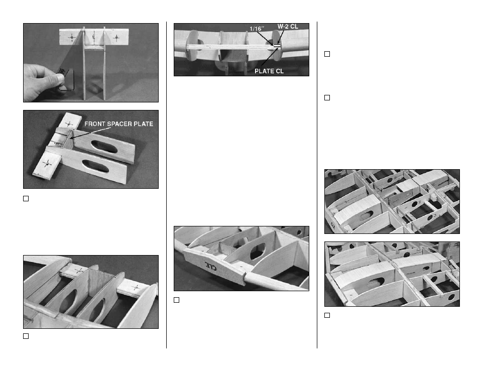
23. Assemble the two die-cut 1/8" plywood
W-1A’s, the die-cut 1/8" plywood Front Spacer
Plate, and the Wing Bolt Plate as shown. Use a
90 deg. triangle to check the alignment. Then
glue the assembly together.
24. See the cross section at W-1 on the
fuselage plan for the proper orientation of the
angle on the front of the W-1A’s. Fit this forward
assembly between the two W-2’s. The aft edges
are centered on the front face of the dihedral
brace (you also may look ahead to the wing
sheeting section to see why the W-1 ribs are
undersized). The front is located by placing the
center of the 1/4" wing bolt plate 1/16" below the
centerline on the W-2’s (toward the bottom
surface of the wing).
25. Glue the two die-cut 3/16" balsa Center
Leading Edges (CLE’s) together with CA. Sand
their length, if necessary, until they fit between
the two wing leading edges in front of the Wing
Bolt Plate. Glue in the CLE’s. You may rough
contour them now, but do the final sanding after
the wing has been sheeted.
SHEET THE WING
1. Sort through the remaining 1/16" x 3" x 36"
wing sheeting. Pick out the best 8 sheets and set
them aside for the top of the wing.
2. Notice that the center wing rib W-1 is 1/16"
undersized everywhere but on top of the aileron
servo. This is to allow you to put 1/16" center
sheeting over the W-1 ribs to reinforce the center-
section.
3. Cut 2" long pieces of sheeting from the
1/16" wing sheeting. Glue the sheeting to the top
and bottom of the two W-1 ribs (except on top of
the aileron servo tray) as shown in the photos.
- 21 -