Top Flite TOPA0110 User Manual
Page 29
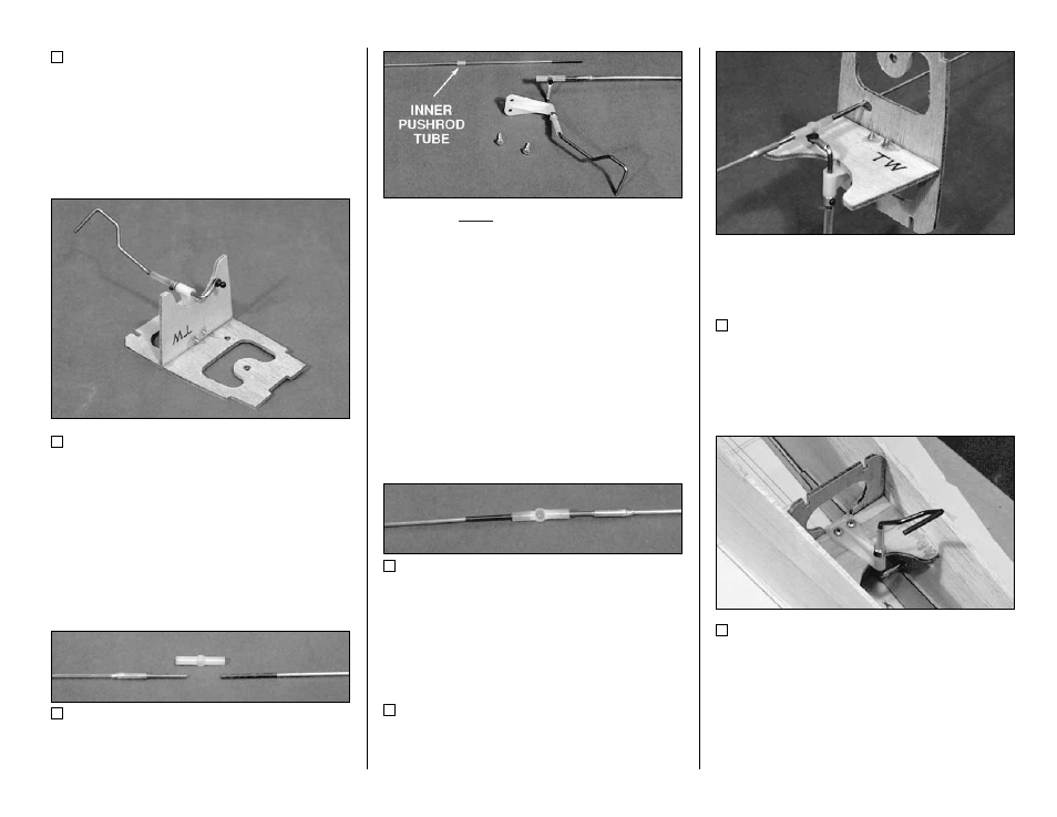
29. Roughen the tubular Nylon Bearing on
the tail wheel wire with sandpaper so glue will
stick to it.
30. Put a small drop of 5-minute epoxy on the
Nylon Bracket where the two bolt holes are.
Screw the Nylon Bracket to TW with two #4 x 3/8"
Sheet Metal Screws. Then put a drop of epoxy
on the threads of the Sheet Metal Screws to
prevent them from loosening.
31. Cut 8" off one end of the .074 x 35"
T h r e a d e d B o t h E n d R o d .
P l a c e a b r a s s
Threaded Coupler over the unthreaded end of
t h e 8 " p i e c e . M e a s u r e t h e l e n g t h o f t h e
assembly. Cut length off the wire until the total
assembled length is 8-1/2". Slide a 5/16" length
of inner pushrod tube over this piece of wire as
shown on the plans. Silver solder the Brass
Coupler to the wire.
32. Screw the Brass Threaded Coupler of the
wire well into one end of the Nylon Two-Ended
Ball Link. Screw the remainder of the 35" rod
that you cut in the previous step into the other
end of the Ball Link.
33. Test fit the pushrod linkage onto the
tailgear assembly. Oblong the rudder pushrod
hole in F-10 sideways to allow for movement (see
next photo).
Adjust the wheel collar height for best alignment
of the pushrod. Apply some threadlocker to the
4-40 set screw and tighten it snugly. Remove the
pushrod.
34. Slide five 5/16" lengths of inner pushrod
over the rudder pushrod and space them as
shown on the plans.
35. Place the F-10/TW assembly in position
between the fuselage sides. It should be located
using the notches in the aft fuse doublers. Work
a piece of masking tape beneath the fuselage and
use it to pull the sides to the formers. Use a 90
deg. triangle to make sure the former is vertical.
Pull the upward facing edges of the fuselage
sides together with another piece of masking
tape.
- 29 -