Top Flite TOPA0110 User Manual
Page 20
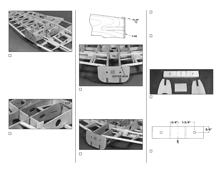
15. Notice that the W-1 ribs in the assembly
are undersized 1/16" (except the area around the
top of the aileron servo) to allow for a center
doubler of 1/16" balsa center sheeting. Put
marks on the dihedral braces 3/4" both ways from
the center of the wing to aid in the alignment of
the center assembly.
16. The front of the assembly is positioned by
aligning the top edge of the assembly with the top
of the dihedral brace. Tack glue the assembly at
the front edge. NOTE: The word “top” refers to
the top surface of the wing.
17. The back end of the assembly is aligned
by centering the flap TE on the top edge of F-8B
a t W - 1 . T h e A f t C r o s s B r a c e ( C B ) s h o u l d
protrude about 1/16" on both sides of the W-1 ribs
to allow for the double sheeting.
18. Thoroughly glue all the joints in the area
of the center assembly with medium CA.
1 9 . M a k e s h e a r w e b s f o r t h e a f t s p a r
between W-1 and W-2. Glue them to the front of
the aft spar with medium CA.
20. Trim the length of the 1/4" plywood
beveled edge Wing Bolt Plate until it fits between
the two W-2’s near their centerline.
21. Mark a centerline on the Wing Bolt Plate.
Mark two lines offset 3/4" on both sides of the
centerline as shown.
22. Mark the wing bolt hole locations as
shown in the sketch above. Drill 13/64" pilot
holes at the locations marked.
- 20 -