Top Flite TOPA0110 User Manual
Page 28
- 28 -
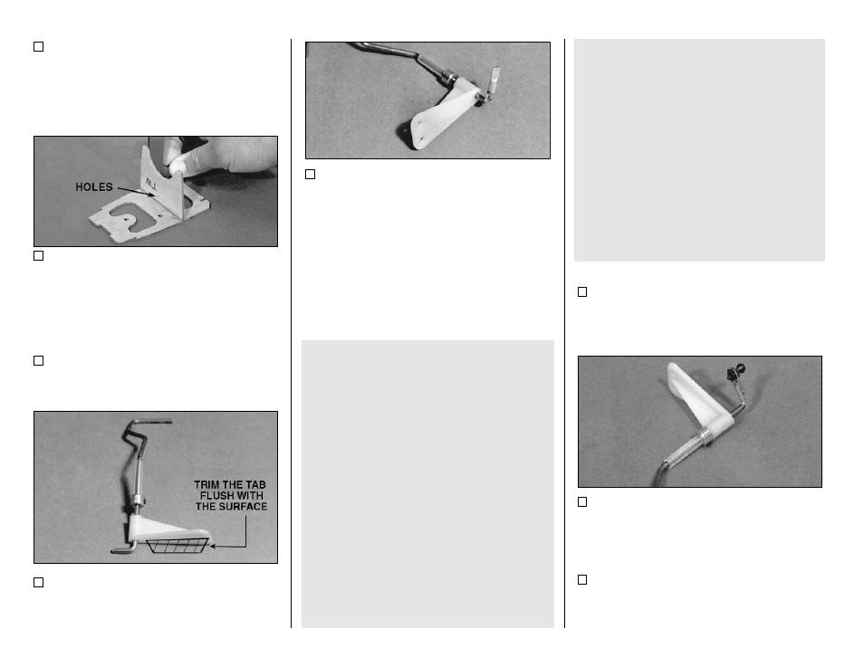
21. Drill 5/64" holes through the two punch
marks in the die-cut 1/8" plywood Tail Wheel
Plate (TW).
22. Glue the die-cut 1/8" plywood Tail Wheel
Plate (TW) to former F-10, making sure they are
perpendicular. Make sure the number on F-10
faces down.
23. If there is an additional vertical web on
the nylon tail wheel bracket, trim it off so the part
resembles the one in the photos.
24. If there is excess length at the top of the
tail wire, trim it off with a cut-off wheel so there is
only about 3/8" remaining after the bend.
25. Place the 5/8" long piece of 1/8" O.D.
b r a s s t u b i n g o v e r t h e t o p e n d o f t h e w i r e .
Squeeze the exposed end of the tube firmly with
pliers to flatten it. Check the parts over the
fuselage top view to make sure they match up
well. Silver solder the brass tube to the top of the
tail wheel wire (see below).
TIPS FOR SILVER SOLDERING
Use this process when soldering metal to metal
such as brass tube to wire, or pushrod ends to
wire.
A. Thoroughly clean the items to be soldered
with alcohol or degreasing solvent.
B. Roughen the area to be soldered with fine
sandpaper. Then clean again.
C. Assemble the items to be soldered.
D. Apply a small amount of soldering flux. Acid
based flux works best when one or more of the
items is steel.
E. Heat the metal with a soldering gun or iron,
and apply solder to the metal. The metal must
get hot enough to melt the solder and the solder
must freely flow into the joint.
F. Do not move the parts until the solder has
cooled.
G. Clean off the excess flux with alcohol or
solvent. Coat the parts with a very fine film of oil.
H. Test the joint by pulling hard.
26. Mark the location of the Metal Ball on the
flat spot. Drill a 1/16" hole at the mark.
27. Attach the ball permanently to the tail
gear with the Small Nut provided. Put a drop of
5-minute epoxy on the threads to prevent it from
vibrating loose.
28. Use the 4-40 Set Screw to set the collar
at the height shown on the fuselage side view, but
orient the set screw so small adjustments can be
made later if required.