Top Flite TOPA0110 User Manual
Page 38
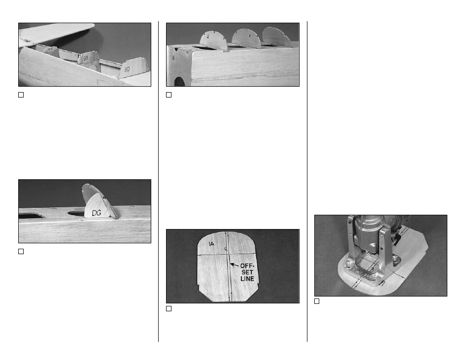
8. Glue the die-cut 1/8" plywood former tops
F-10B, F-9B, and F-8D to the tops of their
respective formers.
9. Use the die-cut 1/8" plywood Dash Gauge
(DG) to set the angle of the die-cut 1/8" former
F-6. Glue in F-6, but do not glue in the gauge.
10. Glue in the die-cut 1/8" plywood former
tops F-4 and F-2.
NOTE: It is easiest to lay out your
engine and mount locations now,
before F-1A is glued on and the deck
sheeting applied. If you do not have
your engine and mount, draw the
centerlines and offset line on F-1A and
continue. You may have to insert blind
nuts through the wing saddle later.
11. There are punch marks in the die-cut 1/8"
plywood former F-1A (firewall). These locate the
firewall centerlines and an offset line. Draw lines
connecting these points as shown in the photo.
NOTE: The same offset line is used,
whether or not spacers are used, since
the 9mm plywood engine mount
spacers project at the same angle as a
longer engine does. The bolt pattern
in the firewall for the mounting of a
shorter engine/mount combination can
be laid out by putting the mount
centerlines on the firewall offset line
and horizontal centerline. The
spacers can be added later.
12. The centerline of the engine is positioned
on the horizontal centerline and the offset line.
The offset line is located on the (pilot’s) left side
of the firewall centerline. This allows the spinner
to be on the centerline of the model, despite the
right thrust.
- 38 -