Reznor VR Unit Installation Manual User Manual
Page 42
Form I-VR, P/N 205202 R13, Page 41
Ignition Controller
Function - The ignition controller functions to ignite the burner and as a flame
supervision device. The ignition controller will shut off main burner gas flow
immediately if the burner flame is lost.
Burner ignition is achieved by a high voltage (18kV) spark that occurs across
the spark electrode. The proper gap and location are important.
CAUTION: Do not attempt to measure flame current signal. Attempting
to do so can result in high voltage shock and/or damage to the meter.
The presence of the flame is detected by the ignition controller’s sensing circuit
when a DC current flows through the spark electrode assembly. A current flow
of at least 1.0 microamps is required for flame detection.
FIGURE 41 - Gas
Valve
FIGURE 40 -
Ignition Controller
Combination Gas
Valve
Combustion Air
Blower System
Function - The function of the combustion air blower system is to provide a
metered flow of air to the burner for proper combustion of the fuel gas. The
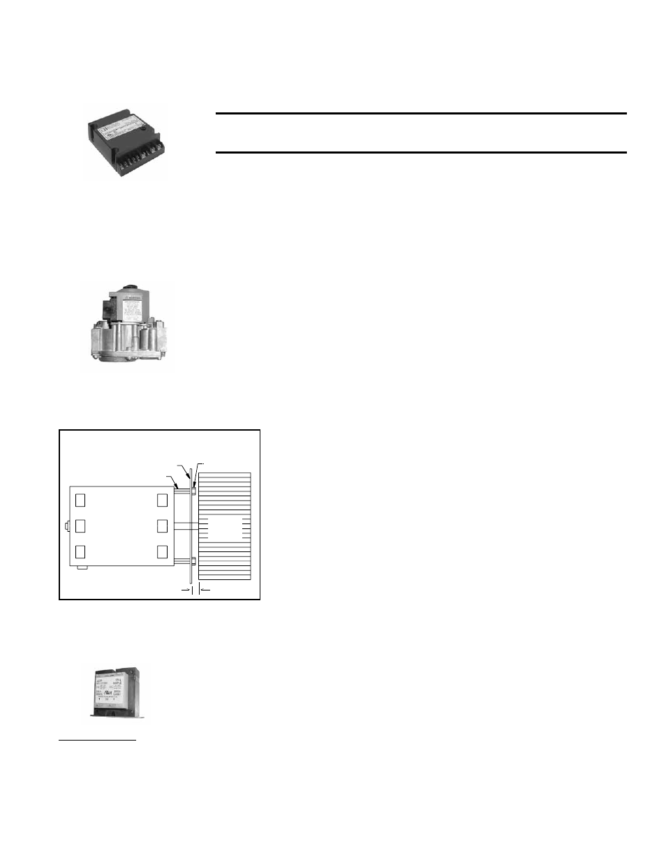
Motor
Wheel
Motor Plate
Fastener (4)
Spacer
5/16 (8mm)
FIGURE 42 - Motor and Wheel
Spacing
quantity of airflow also serves to control the temperature of the radiat-
ing surfaces. The combustion air blower system is comprised of the
combustion air orifice, the blower wheel, the blower housing, and the
blower motor.
Service - This system contains no field serviceable parts. If any com-
ponents become defective, it must be replaced. The blower motor is
permanently oiled and requires no additional oiling. For proper blower
motor operation, the voltage supplied to the motor must be within a
suitable range. If any part(s) must be replaced, the correct blower
wheel spacing must be maintained. Refer to
FIGURE 42 and Mainte-
nance Section, Paragraph 9.2.7. Use only replacement parts identical
to the factory-installed parts.
Transformer
FIGURE 43 -
Transformer
Function - The function of the transformer is to reduce the supply voltage to a
24-volt circuit in order to operate the 24-volt controls.
Transformer Check (requires a voltmeter) - To verify the 24-volt circuit, check-
ing the operation of the transformer, set the thermostat to above room tem-
perature. Using a voltmeter, check the voltage between Terminal R on the ther-
mostat terminal strip (on the burner/control box) and the ground terminal on
the ignition controller. If there is no voltage in this circuit, the transformer is not
functioning. The service of a transformer is like that a of a light bulb; it is either
good or bad, and when bad, it must be replaced.
Service - If replacement of the transformer is necessary, do not substitute any
other transformer. Use a replacement transformer IDENTICAL to the factory-
installed model. The electrical compartment is not intended to be pressurized,
and replacement of another type transformer could cause combustion air leak-
age.
Function - The combination valve provides a number of functions. It automati-
cally controls the gas flow to the burner. It regulates the burner gas pressure;
and it contains a manual valve for complete interruption of the gas flow. The
combination valve also has pressure tap ports for measuring inlet (supply) gas
pressure and manifold gas pressure. See Paragraph 6.3 for proper inlet gas
pressure range and instructions on checking outlet pressure.
Normally, it is not necessary to adjust the manifold gas pressure. Do not attempt
to correct for low inlet (supply) pressure by adjusting the pressure regulator.
Adjusting the pressure regulator on the combination gas valve will not increase
the supply pressure, and if at a later time, the inlet pressure is increased, an
unsafe condition could result. .
Service - The combination valve has no field-repairable parts.
Important Note: To prolong
the life of the transformer,
do not short the “hot” side
of the transformer to ground
when servicing the heater.
Doing so will cause the
transformer to fail.