Mechanical (cont’d), 2 assemble and suspend the heater (cont’d) – Reznor VR Unit Installation Manual User Manual
Page 19
Form I-VR, P/N 205202 R13, Page 18
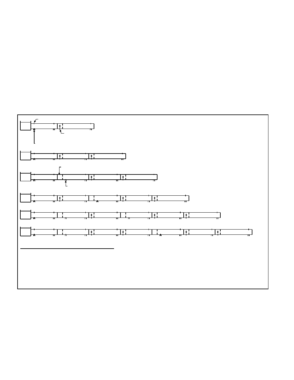
FIGURE 19D -
Reflector Overlaps
(Straight Systems)
Indicates Required Hanging (Suspension) Point
NON-SLIP Overlap (Overlap reflectors 1-1/2 (38mm) and attach on both sides using
one clip and three screws.)
Indicates Reflector Attached to a Tube Bracket (required at the burner box and downstream of each
SLIP overlap)
SLIP Overlap (Reflectors overlap 1-1/2 (38mm) but are not attached.)
NOTE: SLIP overlap applies only to 40, 50, 60, and 70 ft systems.
20 ft
30 ft
40 ft
50 ft
60 ft
70 ft
Downstream of a SLIP overlap, always attach the reflector to a tube bracket.
REFLECTOR OVERLAP REQUIREMENTS:
Size 20 reflectors have one NON-SLIP overlap.
Size 30 reflectors have two NON-SLIP overlaps.
Size 40 reflectors have two NON-SLIP overlaps and one SLIP overlap.
Size 50 reflectors have three NON-SLIP overlaps and one SLIP overlap.
Size 60 reflectors have three NON-SLIP overlaps and two SLIP overlaps.
Size 70 reflectors have four NON-SLIP overlaps and two SLIP overlaps.
No more than two consecutive NON-SLIP overlaps.
No consecutive SLIP overlaps.
“U” or “L” Tube
Reflectors
Follow the instructions in the “U” or “L” option package to assemble and install
the reflector. A “U” tube system can be angled up to 45°. Reflectors on a sys-
tem with an “L” tube cannot be angled.
Side Shields, Options
CD13-22.
Optional side shields are 60-3/4” (1543mm) long pieces of reflector material
that can be “hung” along one side of the heater. When the system is angled,
the side shield must be hung on the lower side. The maximum angle with a side
shield is 30°.
Each side shield section comes with an additional reflector retainer and tube
bracket and two round clips. Side shield kits are designed to extend the full
length of the system with a 3/4” (19mm) overlap, but may be adapted to fit the
installation.
6. Mechanical
(cont’d)
6.2 Assemble and
Suspend the
Heater (cont’d)
6.2.4 Install
Reflectors and
Optional Side Shield
and/or End Covers
(cont’d)
Straight Tube Reflector Installation Instructions (cont’d)
7. SLIP Overlap (One on 40 & 50 ft systems and two on 60 & 70 ft
systems)
Install reflector with a 1-1/2” (38mm) overlap.
Do not screw the reflectors
together.
Immediately downstream of a
SLIP overlap, install a reflector bracket, a U-
bolt, and a reflector retainer. (
NOTE: Suspension is not required.) Secure
both sides of the reflector to the reflector bracket using the screws pro-
vided. Follow the procedure illustrated in
FIGURE 19A.
8. Repeat Step 5, overlapping reflectors 1-1/2” (38mm) until the entire length
of a straight system is covered, making
SLIP or NON-SLIP overlaps as
illustrated in
FIGURE 19D.
If there are “U” or “L” tubes, install their reflector as you come to it before
continuing with the straight reflectors. Follow the instructions packaged
with the “U” or “L” tube.