Maintenance (cont’d) – Reznor VR Unit Installation Manual User Manual
Page 37
Form I-VR, P/N 205202 R13, Page 36
9.2.5 Connection
Couplings
S
Check the bolts and screws on the tube couplings for tightness. Loose
couplings will allow flue products and/or flame to escape into the heated space.
Tighten all bolts and screws. Replace if damaged.
CAUTION: Use of
eye protection is
recommended.
1) Turn off the electrical supply to the heater, open the control access panel,
and rotate the knob on the gas valve to the “OFF” position.
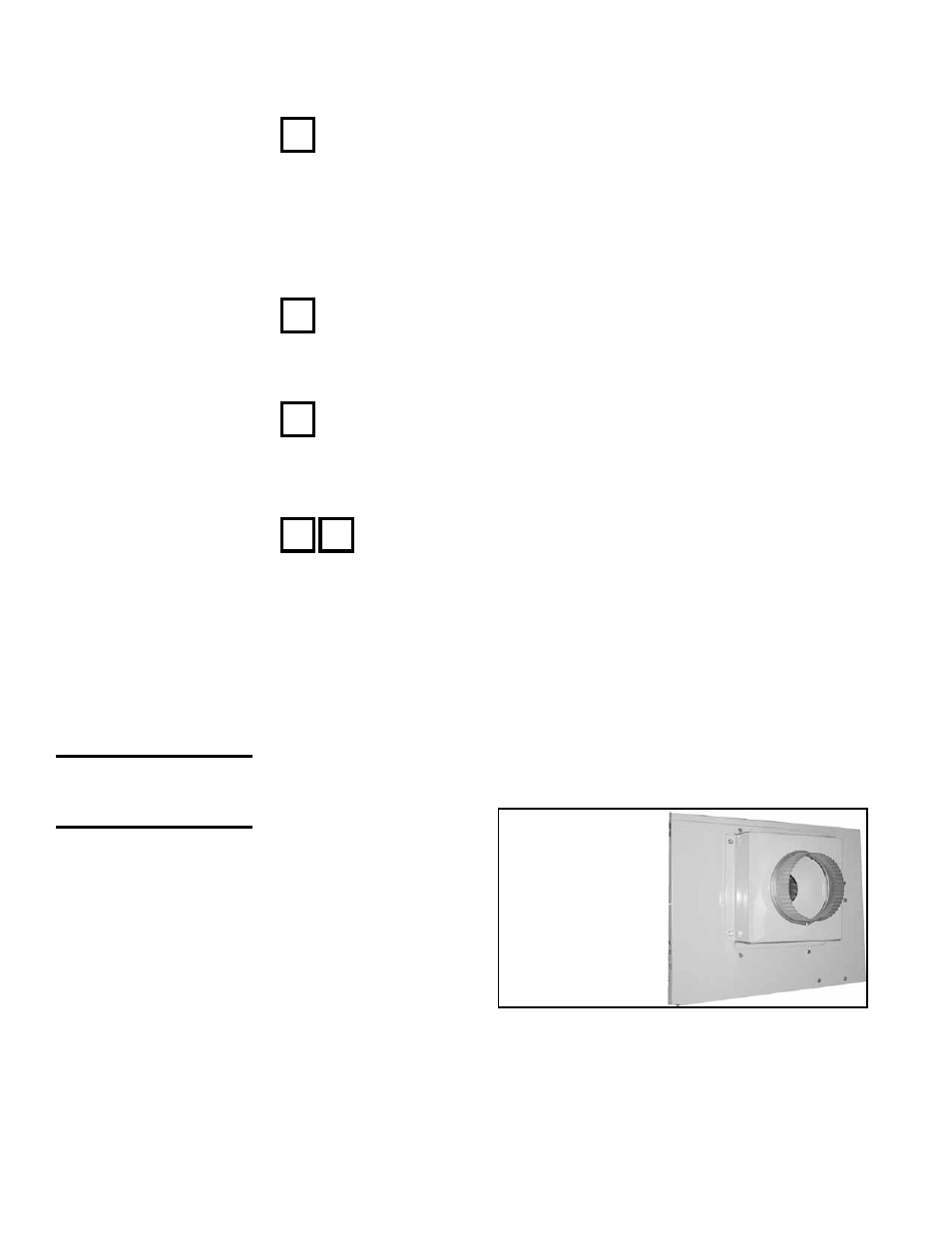
FIGURE 33 -
Combustion Air
Inlet Cover used
with Optional
Outside
Combustion Air
9. Maintenance (cont’d)
9.2 Maintenance Procedures (cont’d)
9.2.6 Vent and/or
Combustion Air
Terminal
R
To prevent the pressure switch from cycling, check the vent terminal
and the combustion air inlet terminal (if equipped with the combustion air inlet
option) for any restrictions and/or damage.
Clean if restricted, and replace if damaged.
9.2.7 Combustion Air
System
R
S
During an average heating season, approximately 65 tons of air pass
through a Size 100 burner. That air is always carrying some dirt. Obviously, the
amount of dirt varies with the environment. As the air passes through, some of
that dirt is deposited on the combustion air intake, on the combustion air blower
wheel, and inside the main burner. This buildup of dirt will eventually affect
the operation of the heater. To maintain safe and reliable heater operation, an
annual cleaning (more frequently in dirty environments) is recommended.
Instructions for Cleaning the Combustion Air Blower (requires a wire
brush, cleaning cloth, and an automotive-type aerosol degreaser or
refrigerant coil cleaner):
3) Open the burner access panel on the bottom of the burner/control box.
Either (1) cover the air inlet to the main burner to prevent foreign debris
from entering the burner tube or (2) remove the burner for cleaning (Refer
to Paragraph 34 on Cleaning the Main Burner).
4) Remove the combustion air restrictor plate (
FIGURE 34) and screen. The
combustion air blower wheel is now visible (
FIGURE 35).
2) If using outside air for
combustion, remove
the combustion air
inlet cover (Refer to
FIGURE 33). It is not
necessary to discon-
nect the pipe. Remove
the inlet cover with the
pipe attached.
S
During a “cold” startup, transient condensation is formed. Over a period
of time, condensation will cause metal pipe to develop holes and eventually fail
completely. Replace any vent pipe that has condensation damage. The vent
pipe system should be maintained at a quality where all flue products will be
conveyed through the vent pipe to the outdoors.
If equipped with an optional dual vent kit, remove the cover from the dual vent
adapter box to check the inner pipe.
9.2.4 Vent Pipe