2 assemble & suspend heater – Reznor VR Unit Installation Manual User Manual
Page 12
Form I-VR, P/N 205202 R13, Page 11
Gas valve adjustment is required for all high altitude operation and can only be
done after the heater is installed. Follow the instructions in Paragraph 6.3.
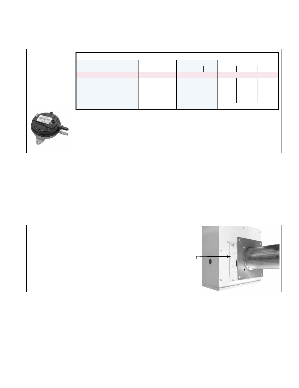
FIGURE 7 -
High Altitude
Pressure
Switch is
Required above
6000 ft (1830 M)
Elevation on
Sizes 50-175
Instructions for Changing Pressure Switch
1. In the control compartment, locate the pressure switch (See
FIGURE 5.)
2. Mark and disconnect the two wires attached to the pressure switch.
3. Disconnect the rubber tubing attached to the pressure switch.
4. Using the same screws, install the high altitude pressure switch for the size of
heater being installed. Attach the rubber tubing and wires.
Additional Burner
Box Preparation for
Operation Above
6000 ft (1830M)
If a Model VR/GVR 50-175 is being installed at an altitude above 6000 ft
(1830M), the pressure switch will have to be changed. If ordered with the unit
as Option DJ20, the pressure switch is shipped separately. (
NOTE: Model
VR200 does not require a pressure switch change above 6000 ft/1830M.)
High Altitude Pressure Switches (Option DJ20 required above 6000 ft/1830M)
Model
VR and GVR
VR
VR and GVR
Size
50 75 100 125 150 175
125
150
175
Electrical Frequency
50 Hz or 60 Hz
60 Hz
50 Hz
Option DJ20 Package P/N
205524
205525
258817 258818 258819
High Altitude Switch P/N
205445
205446
197030 203932 205444
Differential OFF Setpoint
(“ w.c.)
0.15
0.70
0.40
0.25
0.30
Label Color
Gray
Pink
Green
6.2 Assemble and
Suspend the
Heater
6.2.1 Assemble the Burner/Control Box and the Combustion
Chamber Tube
Use these parts (from the hardware bag) to assemble the burner/control box
and the combustion chamber tube: Gasket, P/N 116029; (4) Lockwashers, P/N
1333; (4) Nuts, P/N 6554.
Identify the combustion chamber tube (the aluminized tube with the square
flange on one end). Follow the instructions to attach the combustion chamber
tube to the burner/control box (See
FIGURE 8).
FIGURE 8 - Attach the Combustion Chamber
Tube to the Burner/Control Box
Gasket
6.2.2 Suspend the
Assembled Burner/
Control Box and
Combustion Chamber
Tube
1. Determine location of two combustion chamber tube suspension
points -- one close to the burner/control box and one within 12” (305mm)
of the coupler that will connect it to the first heat exchanger tube. Install a
tube bracket at each suspension point (See
FIGURES 9 and 10). Slide the
threaded “U” bolt over the tube and through the bracket; attach with nuts.
(
NOTE: Nuts must be secure before heater is operated, but if the reflec-
tor is going to be rotated, nuts may be installed loosely now and tightened
later.)
Hook the wire retainer out through the ends of the tube bracket. (
NOTE:
One “hook” of the wire retainer is bent 75° and the other 45°. If the reflector
is going to be rotated, be sure the side with the sharper 45° bend will be at
the lower side.)
a) Slide the gasket over the studs on the burner/
control box.
b) Slide the flange over the bolts.
c) Use the washers and nuts to attach the combustion
chamber flange securely to the burner/control box.