Reznor VR Unit Installation Manual User Manual
Page 15
Form I-VR, P/N 205202 R13, Page 14
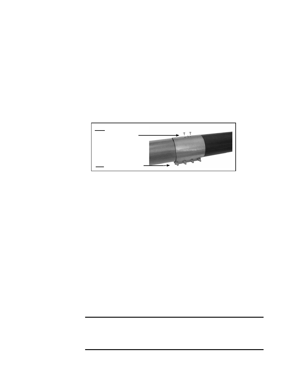
FIGURE 15 - Connect
Combustion
Chamber and Heat
Exchanger Tube
with Compression
Coupling
3. Repeat the instructions in Step No. 2 above to suspend and join all of the
remaining heat exchanger tubes. If installing a “U” or “L” tube, a compression
coupling is used for tube connections but refer to the instructions in the option
package for additional information. Straight tubes adjacent downstream of a
“U” or “L” tube require two suspension points.
NOTE: If your configuration requires a turbulator strip before a “U” or “L” tube,
insert the turbulator strip before the “U” or “L” tube is connected. Follow the
instructions in
Step No. 4, and install two sections of turbulator strip. (This will
only occur when installing a 40’ to 70’ system in a configuration where a “U” or
“L” tube connects directly to the exhaust heat exchanger tube.)
4. Install the Turbulator Strip
Locate turbulator strip sections. Install a turbulator strip in a tube
only after it
has been suspended and connected to the previous tube. Refer to FIG-
URES 16A and 16B. Install the turbulator strip by sliding a section into the
tube, connecting the next section, and sliding the connected sections on into
the tube(s).
Refer to the Turbulator Requirements chart to determine the quantity of turbu-
lator sections required and when and where they should be installed.
1st, Tighten Bolts
2nd, Insert Self-
Drilling Screws
With both tube ends as far into the coupling as they will go, tighten the
coupling bolts. In the top, insert the two self-drilling screws to secure the
coupling to each tube. Use the same procedure to join all heat exchanger
tubes. Tubes must be suspended as they are installed.
Refer to illustrations
in FIGURES as noted.
Follow Steps in order.
with nuts. (NOTE: Nuts must be secure before heater is operated, but if the
reflector is going to be rotated, nuts may be installed loosely now and tight-
ened later.)
Hook the wire retainer out through the ends of the tube bracket. (
NOTE:
One “hook” of the wire retainer is bent 75° and the other 45°. If the reflector
is going to be rotated, be sure the side with the sharper 45° bend will be at
the lower side.)
Slide the hanger bar over the reflector retainer wire. Attach an “S” hook
at the center hole in the bar (See
FIGURE 12). Connect the chain or turn-
buckle from the next suspension point to the “S” hook. Using a turnbuckle
is recommended for leveling.
b) With the bolts toward the bottom, slide the compression coupling onto the
end of the suspended combustion chamber tube. Slide the end of the first
heat exchanger tube into the other side of the coupling. See
FIGURE 15.
6. Mechanical
(cont’d)
6.2 Assemble and
Suspend the
Heater (cont’d)
6.2.3 Install the Heat Exchanger Tubes and Turbulator Strip
Sections (cont’d)
CAUTION: Except for in a 20-ft straight system, turbulator
strips must never be allowed to slide into the combustion
chamber. Verify correct usage of the turbulator strip(s); see
Turbulator Requirements table on page 15.