Reznor VR Unit Installation Manual User Manual
Page 16
Form I-VR, P/N 205202 R13, Page 15
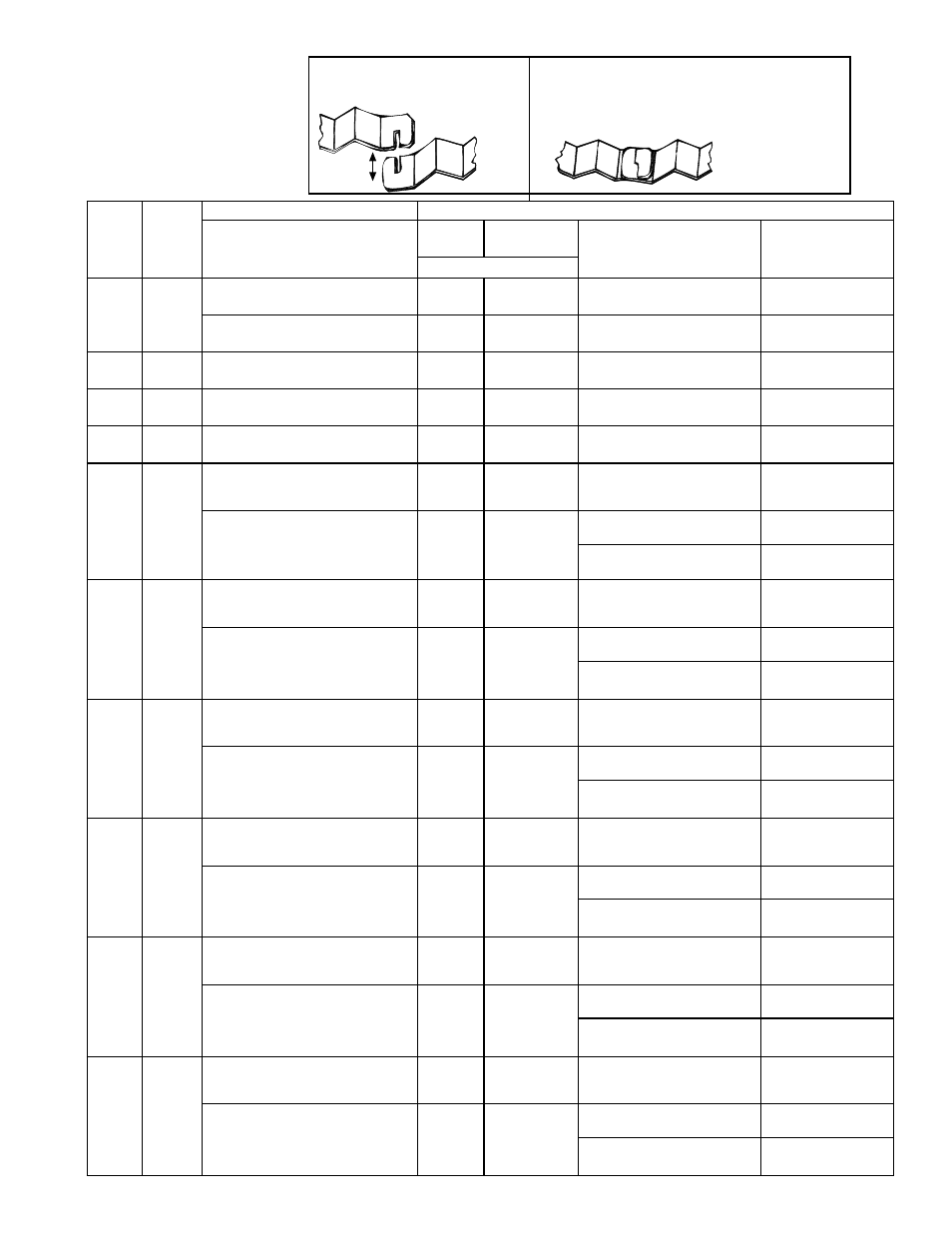
Figure 16A - Turbulator
Strip Sections
FIGURES 16A and
16B - Interlocking
Turbulator Strip
Sections
Figure 16B - As turbulator strip is
installed in the tube, interlock the
sections.
Turbulator
Requirements
Length
of
Straight
Tubes
BTUH
Size
(000)
Configuration
Turbulator Sections
(Some sections may not be used; follow instructions.)
(See Requirements in Paragraph 6;
allowable layouts are illustrated in
Form T-VR-CNFG.)
In Tube
Packages
Used in the
Configuration Quantity and WHEN to Install
(same for all elevations)
WHERE to Install
Number of Sections (qty)
20 ft
50, 75
Straight
4
4
4 sections after exhaust heat
exchanger tube is connected
Into exhaust heat
exchanger tube
“U” or “L”
4
3
3 sections after exhaust heat
exchanger tube is connected
Into exhaust heat
exchanger tube
25 ft
50, 75,
100
All
4
3
3 sections after exhaust heat
exchanger tube is connected
Into exhaust heat
exchanger tube
30 ft
50, 75,
100, 125 All
3
3
3 sections after exhaust heat
exchanger tube is connected
Into exhaust heat
exchanger tube
35 ft
50, 75,
100, 125 All
3
3
3 sections after exhaust heat
exchanger tube is connected
Into exhaust heat
exchanger tube
40 ft
50, 75,
100,
125,
150, 175
Straight heat exchanger tube
adjacent to the exhaust heat
exchanger tube (See
FIGURE 17A)
5
5
5 sections after exhaust heat
exchanger tube is connected
Into exhaust heat
exchanger tube
“U” or “L” tube adjacent to the
exhaust heat exchanger tube (See
FIGURE 17B)
5
5
2 sections before “U” or “L” is
connected
Into end of straight
tube before “U” or “L”
3 sections after exhaust heat
exchanger tube is connected
Into exhaust heat
exchanger tube
45 ft
100,
125,
150,
175, 200
Straight heat exchanger tube
adjacent to the exhaust heat
exchanger tube (See
FIGURE 17A)
5
5
5 sections after exhaust heat
exchanger tube is connected
Into exhaust heat
exchanger tube
“U” or “L” tube adjacent to the
exhaust heat exchanger tube (See
FIGURE 17B)
5
5
2 sections before “U” or “L” is
connected
Into end of straight
tube before “U” or “L”
3 sections after exhaust heat
exchanger tube is connected
Into exhaust heat
exchanger tube
50 ft
100,
125,
150,
175, 200
Straight heat exchanger tube
adjacent to the exhaust heat
exchanger tube (See
FIGURE 17A)
6
5
5 sections after exhaust heat
exchanger tube is connected
Into exhaust heat
exchanger tube
“U” or “L” tube adjacent to the
exhaust heat exchanger tube (See
FIGURE 17B)
6
5
2 sections before “U” or “L” is
connected
Into end of straight
tube before “U” or “L”
3 sections after exhaust heat
exchanger tube is connected
Into exhaust heat
exchanger tube
55 ft
125,
150,
175, 200
Straight heat exchanger tube
adjacent to the exhaust heat
exchanger tube (See
FIGURE 17A)
6
5
All 5 sections after exhaust
heat exchanger tube is
connected
Into exhaust heat
exchanger tube
“U” or “L” tube adjacent to the
exhaust heat exchanger tube (See
FIGURE 17B)
6
5
2 sections before “U” or “L” is
connected
Into end of straight
tube before “U” or “L”
3 sections after exhaust heat
exchanger tube is connected
Into exhaust heat
exchanger tube
60 ft
125,
150,
175, 200
Straight heat exchanger tube
adjacent to the exhaust heat
exchanger tube (See
FIGURE 17A)
5
5
5 sections after exhaust heat
exchanger tube is connected
Into exhaust heat
exchanger tube
“U” or “L” tube adjacent to the
exhaust heat exchanger tube (See
FIGURE 17B)
5
5
2 sections before “U” or “L” is
connected
Into end of straight
tube before “U” or “L”
3 sections after exhaust heat
exchanger tube is connected
Into exhaust heat
exchanger tube
65 or
70 ft
175, 200
Straight heat exchanger tube
adjacent to the exhaust heat
exchanger tube (See
FIGURE 17A)
5
5
5 sections after exhaust heat
exchanger tube is connected
Into exhaust heat
exchanger tube
“U” or “L” tube adjacent to the
exhaust heat exchanger tube (See
FIGURE 17B)
5
5
2 sections before “U” or “L” is
connected
Into end of straight
tube before “U” or “L”
3 sections after exhaust heat
exchanger tube is connected
Into exhaust heat
exchanger tube