Index, 0 roof curbs for models ydha, ydma, ydsa cont'd – Reznor ADFH Option - Installation - Roof Curbs Assembly User Manual
Page 38
Form I-OPT-C, Page 38
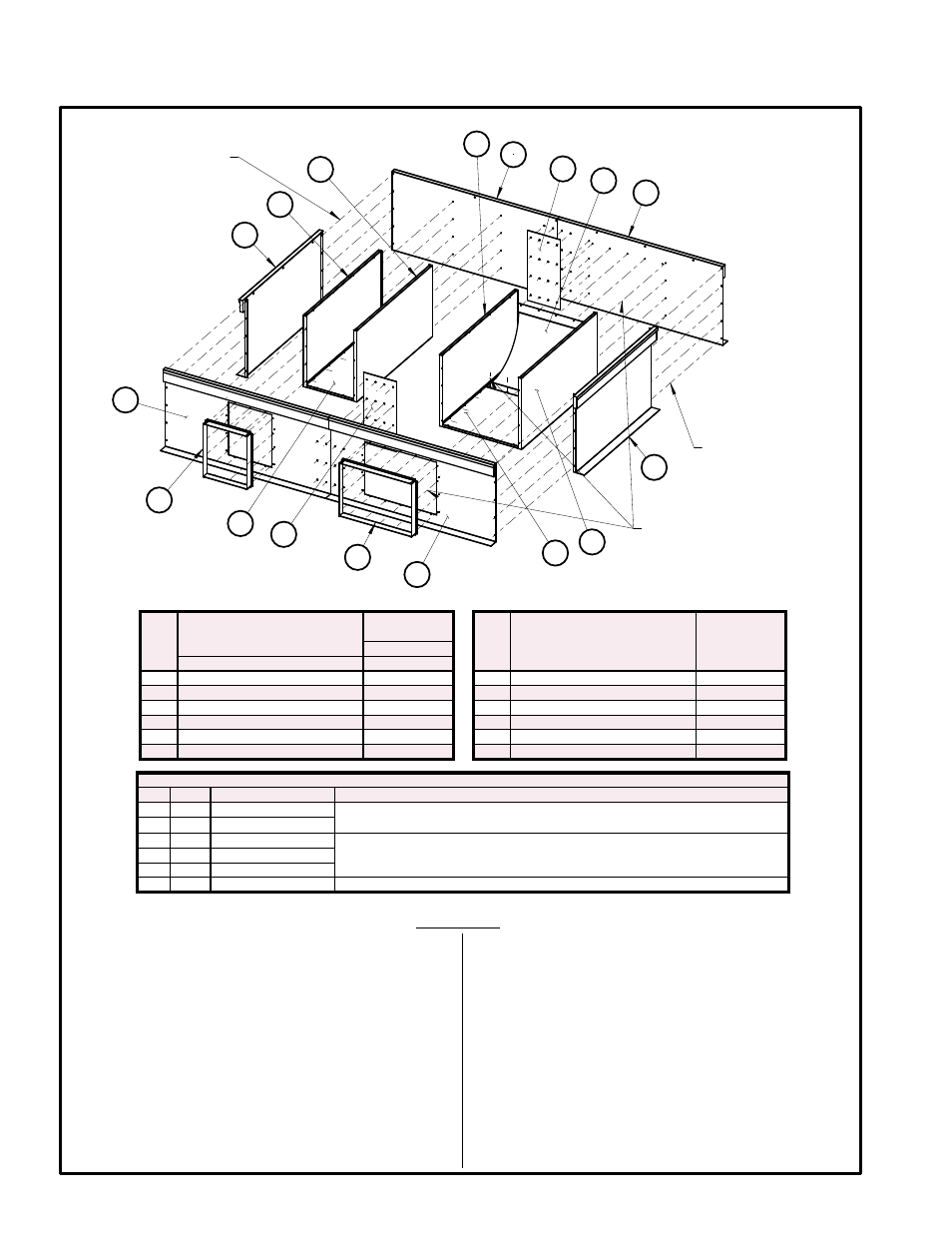
7.0 Roof Curbs for Models YDHA, YDMA, YDSA cont'd
7.2 Roof Curbs for Horizontal Airflow - Options CJ48 & CJ55 cont'd
Lag Screw P/N 16243
Lock Washer P/N 1333
(Qty 12 each)
Wood nailer side - screw
head towards panel
Sheetmetal Screw P/N 11813
(Qty 98)
Cap Screw P/N 16247
Lock Washer P/N 1333
Hex Nut P/N 1035
(Qty 40 each)
Cap screw to be on
insulation side
A
B
G
D
F
C
E
F
G
G
G
H
J
K
L
M
A
Return Air
Supply Air
Item
Description
Curb Option
CJ48 or CJ55
Item
Description
Curb Option
CJ48 or CJ55
Cabinet 3
Cabinet 3
Package P/N
284224
A End Assembly
(2) 284173
G Sides for Plenum Ducts
(4) 284175
B Side Assy (solid/control end)
(1) 284137
H Plenum Duct Bottom
(1) 284181
C Side Assy w/Supply Air Opening
(1) 284139
J
Air Baffle for Supply Air Plenum
(1) 284184
D Side Assy (solid/inlet air end)
(1) 284135
K Return Air Duct Bottom
(1) 284207
E
Side Assy w/Return Air Opening
(1) 284171
L
Return Air Duct Flange
(1) 284185
F
Splice Plates for Sides
(2) 271379
M Supply Air Duct Flange
(1) 271403
Hardware in Options CJ48 & CJ55 for Cabinet 3
Qty P/N Description
Use
12 16243 Lag Screw
For top level screws (1 each corner; 4 each splice plate). Insert screws from
inside the curb so that they extend into the wood nailer on the outside.
12 1333 Lock Washer
40 16247 Cap Screw
For attaching corners and splice plates below the wood nailer (4 each corner; 12
each splice plate). Insert screws from outside the curb.
40 1333 Lock Washer
40 1035 Hex Nut
98 11813 Sheet metal Screws For attaching duct plenum sides, bottom, and baffle; and duct flanges.
1. Refer to FIGURE 14C shown above and position the
two curb ends
(letter A) and four side pieces (letters
B, C, D, E). Verify the side pieces are positioned cor-
rectly (shorter piece at the inlet air end and longer
piece at the control end of the unit).
2. Attach Curb Corners.
Using the hardware provided (lag screw and washer
in top holes; cap screw, washer, and nut in the 4
holes below the wood nailer), create the four corners
by attaching the ends to the side pieces.
3. Attach the two Side Splice Plates (letter F).
Use the hardware provided (lag screw and washer in
top holes; cap screw, washer, and nut in the 4 holes
below the wood nailer) to attach splice plates (
letter
F) joining the side pieces (letters B&D and letters
C&E) to complete the perimeter of the curb.
4. Assemble the Return Air Plenum.
Position two sides
(letter G) between the return air
duct bottom
(letter K) align the holes in each and
using the sheet metal screws, assemble these three
sheet metal pieces. Then using the holes in the curb
sides
(letters D & E), align the return air plenum sub
assembly holes on each end with the holes in the
curb sides and attach using the sheet metal screws.
Installation Instructions for Cabinet Size 3 Horizontal Curb, Option CJ48 and Option CJ55
FIGURE 14C - Cabinet Size 3 Components (Horizontal Curb Options CJ48 and CJ55)
- RCB Option - Installation - Roof Curbs Assembly RDB Option - Installation - Roof Curbs Assembly RDC Option - Installation - Roof Curbs Assembly RDCB Option - Installation - Roof Curbs Assembly RDCC Option - Installation - Roof Curbs Assembly RDDB Option - Installation - Roof Curbs Assembly RCC Option - Installation - Roof Curbs Assembly RDDC Option - Installation - Roof Curbs Assembly RECB Option - Installation - Roof Curbs Assembly RECC Option - Installation - Roof Curbs Assembly REDB Option - Installation - Roof Curbs Assembly REDC Option - Installation - Roof Curbs Assembly RDF Option - Installation - Roof Curbs Assembly RDH Option - Installation - Roof Curbs Assembly REH Option - Installation - Roof Curbs Assembly RHH Option - Installation - Roof Curbs Assembly RXH Option - Installation - Roof Curbs Assembly RPB Option - Installation - Roof Curbs Assembly RPBL Option - Installation - Roof Curbs Assembly RPDBL Option - Installation - Roof Curbs Assembly YDSA Option - Installation - Roof Curbs Assembly YDMA Option - Installation - Roof Curbs Assembly YDHA Option - Installation - Roof Curbs Assembly RBL Option - Installation - Roof Curbs Assembly ADF Option - Installation - Roof Curbs Assembly