Reznor ADFH Option - Installation - Roof Curbs Assembly User Manual
Page 31
Form I-OPT-C, P/N 132900 R17, Page 31
Roof Curb
Hardware
and Tape
For
Top 2 Corner "Holes"
(8) 5/16"x1" Lag Screws,
P/N 16243; (8) 5/16" Lockwasher, P/N 1333
For
Bottom 2 Corner
"Holes"
(8) 5/16"x3/4" Hex Head Cap Screw,
P/N 16247; (8) 5/16" Lockwasher, P/N 1333; (8) 5/16-18
Hex Nut,
P/N 1035
Hardware to Assemble & Attach Dividers (64) #10 Sheetmetal Screws, P/N 11813
(1) 1/4" x 1-1/4" x 50ft Foam Sealant Tape,
P/N 66302
1. If installing an Option CJ3 curb, follow these instructions. If installing a field-sup-
plied curb, the curb must be level and must be sealed to the system curb cap.
2. Position the roof curb end assemblies and side assemblies as shown in the draw-
ing in
FIGURE 12A, (Items A and B). Fasten with bolts and lag screws as illus-
trated in the corner detail (
FIGURE 12C).
3. If the system has a bottom discharge and/or a return air inlet, use the sheetmetal
screws to sub-assemble the dividers
(Items C, D, and E). Refer to the dimen-
sions in
FIGURE 12B to appropriately position the roof curb dividers to create the
needed duct opening flanges. Attach the dividers to the roof curb with sheetmetal
screws.
NOTE: If the system does not have a bottom discharge and/or a return air
opening, the dividers for an opening that is not going to be used may be installed
but are not required.
4. Check the assembly for squareness. The curb must be adjusted so that the diago-
nal measurements are equal within a tolerance of ±1/8” (±3 mm).
5. Level the roof curb. To ensure a good weatherproof seal between the unit curb cap
and the roof curb, the roof curb must be leveled in both directions with no twist end
to end. Shim as required and secure curb to the roof deck before installing flashing
(See Curb Detail in
FIGURE 12C).
6. Install field-supplied flashing.
7. Before placing the unit on the curb:
□
If ductwork is being installed from the top, slide the ductwork down into the dis-
charge and return air openings. See dimensions in
FIGURE 12B. Ductwork should
be sized slightly smaller with a minimum 3/4" duct flange that can be attached
to all sides of the duct connection. See the unit installation manual for ductwork
requirements
□
Apply 1/4" x 1-1/4" foam sealant tape to both the top surface of the curb rails and
the top surface of the perimeter of the duct opening(s), being sure to make good
butt joints at all corners. The sealant tape must be applied to prevent water leak-
age into the curb area due to blown rain and capillary action.
□
When it is time to lift the unit onto the prepared curb, be sure that all of the above
preparations have been made.
IMPORTANT: Verify that the unit will be placed in
the correct airflow orientation to mate properly with the discharge and return air
openings.
INSTALLATION
INSTRUCTIONS for
Model RDF Roof Curbs
CAUTION: Before
installation,
recheck to be
sure that the
correct curb has
been ordered.
Be sure that the
curb selected
matches the unit
ordered. Verify the
dimensions of the
curb received with
the dimensions on
page 30.
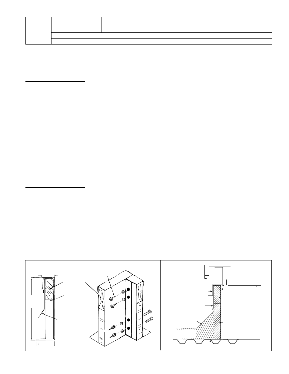
Curb Cap
Counter Flashing
(by installer)
Cant Strip
(by installer)
MUST be sealed
between curb cap
and roof curb
2 x 6
Wood
Nailer
Insulation
16
(406 mm)
Curb Height
Cabinet
Curb Cap Skirt
Weld, bolt, or lag screw curb to deck structure.
Roof Curb
Roofing Felts
(by others)
16
(406mm)
1-7/8(48mm)
4 (102mm)
2 x 6 Wood
Nailer
1-1/2 x 3 lb
Fiberglass
Flashed by the
installer (flashing
must be under
lip of curb)
Lag Screws
Cap
Screws
Typical
Curb Detail
Curb Section and Corner Detail
FIGURE 12C - Curb Assembly for Model RDF
- RCB Option - Installation - Roof Curbs Assembly RDB Option - Installation - Roof Curbs Assembly RDC Option - Installation - Roof Curbs Assembly RDCB Option - Installation - Roof Curbs Assembly RDCC Option - Installation - Roof Curbs Assembly RDDB Option - Installation - Roof Curbs Assembly RCC Option - Installation - Roof Curbs Assembly RDDC Option - Installation - Roof Curbs Assembly RECB Option - Installation - Roof Curbs Assembly RECC Option - Installation - Roof Curbs Assembly REDB Option - Installation - Roof Curbs Assembly REDC Option - Installation - Roof Curbs Assembly RDF Option - Installation - Roof Curbs Assembly RDH Option - Installation - Roof Curbs Assembly REH Option - Installation - Roof Curbs Assembly RHH Option - Installation - Roof Curbs Assembly RXH Option - Installation - Roof Curbs Assembly RPB Option - Installation - Roof Curbs Assembly RPBL Option - Installation - Roof Curbs Assembly RPDBL Option - Installation - Roof Curbs Assembly YDSA Option - Installation - Roof Curbs Assembly YDMA Option - Installation - Roof Curbs Assembly YDHA Option - Installation - Roof Curbs Assembly RBL Option - Installation - Roof Curbs Assembly ADF Option - Installation - Roof Curbs Assembly