Figure 5b - option cj3 roof curb assembly for maps, Iii cabinet d – Reznor ADFH Option - Installation - Roof Curbs Assembly User Manual
Page 15
Form I-OPT-C, P/N 132900 R17, Page 15
4. Return Air Duct Supports - Position the two return air side supports
and the end support as shown in
FIGURES 5A and 5D. Follow STEP
7 in
FIGURE 5B to attach.
5. Check the roof curb for squareness. The curb must be adjusted so
that the diagonal measurements are equal within a tolerance of ± 1/8"
(3mm).
6. Level the roof curb. To ensure a good weatherproof seal between the
cabinet curb cap and the roof curb, the curb must be leveled in both
directions with no twist end to end. Shim as required and secure curb
to the roof deck before installing flashing.
7. Install field-supplied flashing. See FIGURE 5C.
8. If the unit has return air and/or down discharge, insert ductwork into
the duct openings. See ductwork sizes in
FIGURE 5E.
9. Before placing the unit on the curb:
□
If ductwork is being installed from the top, slide the ductwork down into
the discharge and return air openings. See dimensions in
FIGURE 5E.
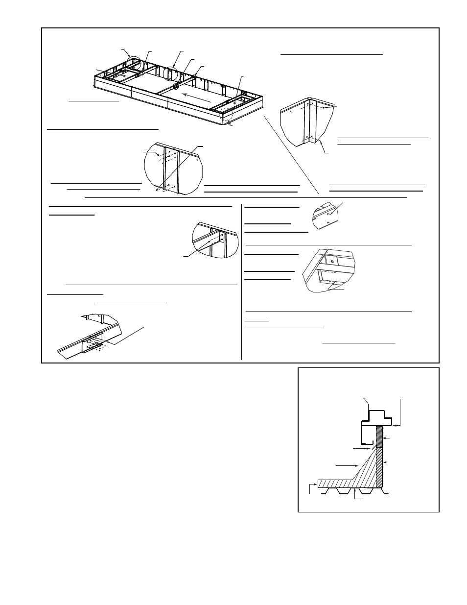
FIGURE 5B - Option CJ3 Roof Curb Assembly for MAPS
®
III Cabinet D
STEP 1 - Detail A - Curb Corner
Position rails as illustrated. If installing Pkg
P/N 220342, be sure to put the two longer
rail side pieces at the return air end.
Position the angle support in the corner and
attach with hardware as illustrated.
Hardware used for 4 Corner Tops:
(8) 2-1/2” Cap Screws, P/N 163334
(8) Lock Washers, P/N 15119
(8) Hex Nuts, P/N 15117
TOP - Cap screw heads should be
on the wood side of the rail.
Hardware used for 4 Corner Bottoms:
(8) 3/4” Cap Screws, P/N 163335
(8) Lock Washers, P/N 15119
(8) Hex Nuts, P/N 15117
BOTTOM - Cap screw heads should
be on the insulation side of the rail.
STEP 2 - Detail B - Rail Side Seam
Connect rail side pieces with the support channels
and hardware as illustrated.
Hardware used for 4 Seams (Top):
(16) 2-1/2” Cap Screws, P/N 163334
(16) Lock Washers, P/N 15119
(16) Hex Nuts, P/N 15117
TOP - Cap screw heads should be
on the wood side of the rail.
Hardware used for
4 Seams (Bottom):
(8) 3/4” Cap Screws, P/N 163335
(8) Lock Washers, P/N 15119
(8) Hex Nuts, P/N 15117
BOTTOM - Cap screw heads should
be on the insulation side of the rail.
STEP 3 - Detail C - Attaching 8 Cross Support Pieces to
the Side Rails (See FIGURE 5D for locations.)
Determine locations of the four cross supports;
dimensions are in FIGURE 5D, page 16
Follow the instructions to attach the ends of all 8
center cross support pieces (4 cross supports;
each with two pieces)
1) Remove the two screws at the
top of the curb rail.
STEP 4 - Detail D - Attaching Splicing Bracket to Connect
Centers of the Four Cross Supports (NOTE: If splice is in a
duct opening, bracket MUST NOT BE INSIDE the opening.)
Hardware for attaching the four
Splicing Brackets:
(32) 3/4” Cap Screws, P/N 163335
(32) Lock Washers, P/N 15119
(32) Hex Nuts, P/N 15117
Curb Assembly
See Dimensions in
FIGURE 5D on page 16.
See Detail A
See
Detail E
See Detail B
See Detail D
See Detail C
STEP 5 - Detail E -
Attaching the Two
Discharge Air
Duct Side Supports
to Curb Cross Supports
See FIGURE 5D; position and
attach the two discharge duct
side supports “inside” the curb
cross supports.
(8) 1/4-20 x 5/8 Bolts, P/N 47252
(8) 1/4-20 Hex Nuts, P/N 7328
Discharge
Duct Opening
Return Air
Opening
STEP 6 - Detail F -
Attaching Two
Return Air Duct
Side Supports
to Curb Rail
(one end of
each support)
See Detail F
(4) 1/4-28 x 2-1/2 Bolt, P/N 114485
(4) Hex Nut 1/4-28, P/N 114486
(4) Lock Washers, P/N 96854
STEP 7
- Repeat Detail E (STEP 5) to attach the opposite ends of the
return air duct side supports (attached in STEP 6) to the cross support.
Repeat Detail E (STEP 5) again to complete the return air duct support
by attaching each end of the return air duct end support to the installed
side supports.
(8) 1/4-20 x 5/8 Bolts, P/N 47252; (8) 1/4-20 Hex Nuts, P/N 7328
2) Position the cross support at the top of the curb as illustrated.
3) Re-insert screws attaching the cross support.
Unit Airflow
Ductwork should be sized slightly smaller with a minimum 3/4" duct flange that can be attached on all sides of the
duct connection. See the system installation manual for ductwork requirements
□
Apply 1/4" x 1-1/4" foam sealant tape to both the top surface of the curb rails and the top surface of the perimeter of
the dividers, being sure to make good butt joints at all corners. The sealant tape must be applied to prevent water
leakage into the curb area due to blown rain and capillary action.
Roofing
Felts (by others)
Cant Strip
(by installer)
Counter Flashing
(by installer)
MUST be
sealed
between
curb cap and
roof curb.
2 x 6
Wood
Nailer
Insulation
Weld, bolt, or lag screw
curb to deck structure.
Curb
Cap
Cabinet W
all
Roof Curb
FIGURE 5C - Cross Section of
Roof Curb Installation
- RCB Option - Installation - Roof Curbs Assembly RDB Option - Installation - Roof Curbs Assembly RDC Option - Installation - Roof Curbs Assembly RDCB Option - Installation - Roof Curbs Assembly RDCC Option - Installation - Roof Curbs Assembly RDDB Option - Installation - Roof Curbs Assembly RCC Option - Installation - Roof Curbs Assembly RDDC Option - Installation - Roof Curbs Assembly RECB Option - Installation - Roof Curbs Assembly RECC Option - Installation - Roof Curbs Assembly REDB Option - Installation - Roof Curbs Assembly REDC Option - Installation - Roof Curbs Assembly RDF Option - Installation - Roof Curbs Assembly RDH Option - Installation - Roof Curbs Assembly REH Option - Installation - Roof Curbs Assembly RHH Option - Installation - Roof Curbs Assembly RXH Option - Installation - Roof Curbs Assembly RPB Option - Installation - Roof Curbs Assembly RPBL Option - Installation - Roof Curbs Assembly RPDBL Option - Installation - Roof Curbs Assembly YDSA Option - Installation - Roof Curbs Assembly YDMA Option - Installation - Roof Curbs Assembly YDHA Option - Installation - Roof Curbs Assembly RBL Option - Installation - Roof Curbs Assembly ADF Option - Installation - Roof Curbs Assembly