Reznor ADFH Option - Installation - Roof Curbs Assembly User Manual
Page 34
Form I-OPT-C, Page 34
7.1 Downflow Roof Curbs cont'd
7.0 Roof Curbs for Models YDHA, YDMA, YDSA cont'd
Installation Instructions for Down Discharge Roof Curb, Option CJ31 and Option CJ34
1. Refer to FIGURE 13B shown on page 33 and layout
the two curb ends
(Item D) and four side pieces
(Items B&C). Verify that the side pieces are in the
correct positions (inlet air end versus control end).
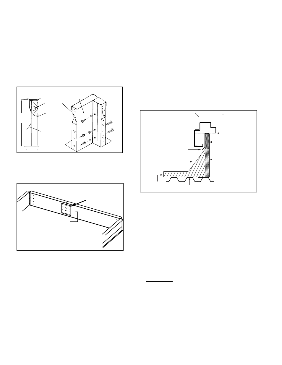
2. Attach Curb Corners as shown below in FIGURE 13C.
Using the hardware provided, create the corners by
attaching the ends to the side pieces.
16
(406mm)
1-7/8(48mm)
4 (102mm)
2 x 6 Wood
Nailer
1-1/2 x 3 lb
Fiberglass
Flashed by the
installer (flashing
must be under
lip of curb)
Lag Screw
and
Washer
Cap
Screws
3. Attach the Splice Plates (Item E) as shown below
in FIGURE 13D
Use the hardware provided to attach splice plates to
join the side rail pieces and create the perimeter of the
curb.
(4) Lag Screws with
washers - top row
(into the nailer)
}
(12) Cap Screws
with washers and nuts
- bottom three rows (cap screw heads
should be on insulation side of rail)
4. Attach the four Cross Supports (Item A).
At the holes in curb sides, line up the cross supports in
the orientation illustrated in
FIGURE 13B as shown on
page 33. Since the cross supports form the duct con-
nections, be certain that the vertical side of each cross
support is toward the duct opening.
Using two lag screws with washers, at each end of a
cross support, attach the support to the sides. Insert
the screws through the side and into the wood nailer.
Repeat for the other three cross supports.
5. Check the roof curb for squareness.
Adjust the curb so that the diagonal measurements
are equal within a tolerance of ±1/8”(3mm).
6. Level the roof curb.
To ensure a good weatherproof seal between the
cabinet curb cap and the roof curb, the curb must be
leveled in both directions with no twist end to end.
Shim as required and secure curb to the roof deck
before installing flashing.
7. Install field-supplied flashing as shown below in
Figure 13E.
Roofing
Felts (by others)
Cant Strip
(by installer)
Counter Flashing
(by installer)
MUST be
sealed
between
curb cap and
roof curb.
2 x 6
Wood
Nailer
Insulation
Weld, bolt, or lag screw
curb to deck structure.
Curb
Cap
Cabinet W
all
Roof Curb
}
8. Before placing the unit on the curb:
□
Apply 1/4” x 1-1/4” foam sealant tape to both the top
surface of the curb rails and the top surface of the
cross supports, being sure to make good butt joints
at all corners. The sealant tape must be applied to
prevent water leakage into the curb area due to blown
rain and capillary action.
□
Slide the ductwork down into the supply (discharge)
and optional return air openings. See dimensions in
FIGURE 13A shown on page 32. Ductwork should
have a minimum 2” (51mm) duct flange.
□
When it is time to lift the unit onto the prepared curb,
be sure that all of the above preparations have been
made.
IMPORTANT: Verify that the unit will be placed in the
correct airflow orientation to mate properly with the
discharge and return air openings.
FIGURE 13D - Attaching Spice Plates
FIGURE 13E -
Installed Curb
FIGURE 13C - Curb Detail and Corner
- RCB Option - Installation - Roof Curbs Assembly RDB Option - Installation - Roof Curbs Assembly RDC Option - Installation - Roof Curbs Assembly RDCB Option - Installation - Roof Curbs Assembly RDCC Option - Installation - Roof Curbs Assembly RDDB Option - Installation - Roof Curbs Assembly RCC Option - Installation - Roof Curbs Assembly RDDC Option - Installation - Roof Curbs Assembly RECB Option - Installation - Roof Curbs Assembly RECC Option - Installation - Roof Curbs Assembly REDB Option - Installation - Roof Curbs Assembly REDC Option - Installation - Roof Curbs Assembly RDF Option - Installation - Roof Curbs Assembly RDH Option - Installation - Roof Curbs Assembly REH Option - Installation - Roof Curbs Assembly RHH Option - Installation - Roof Curbs Assembly RXH Option - Installation - Roof Curbs Assembly RPB Option - Installation - Roof Curbs Assembly RPBL Option - Installation - Roof Curbs Assembly RPDBL Option - Installation - Roof Curbs Assembly YDSA Option - Installation - Roof Curbs Assembly YDMA Option - Installation - Roof Curbs Assembly YDHA Option - Installation - Roof Curbs Assembly RBL Option - Installation - Roof Curbs Assembly ADF Option - Installation - Roof Curbs Assembly