Roof curb, 0 roof curbs for z series model zqyra (cont'd) – Reznor ADFH Option - Installation - Roof Curbs Assembly User Manual
Page 18
Form I-OPT-C, Page 18
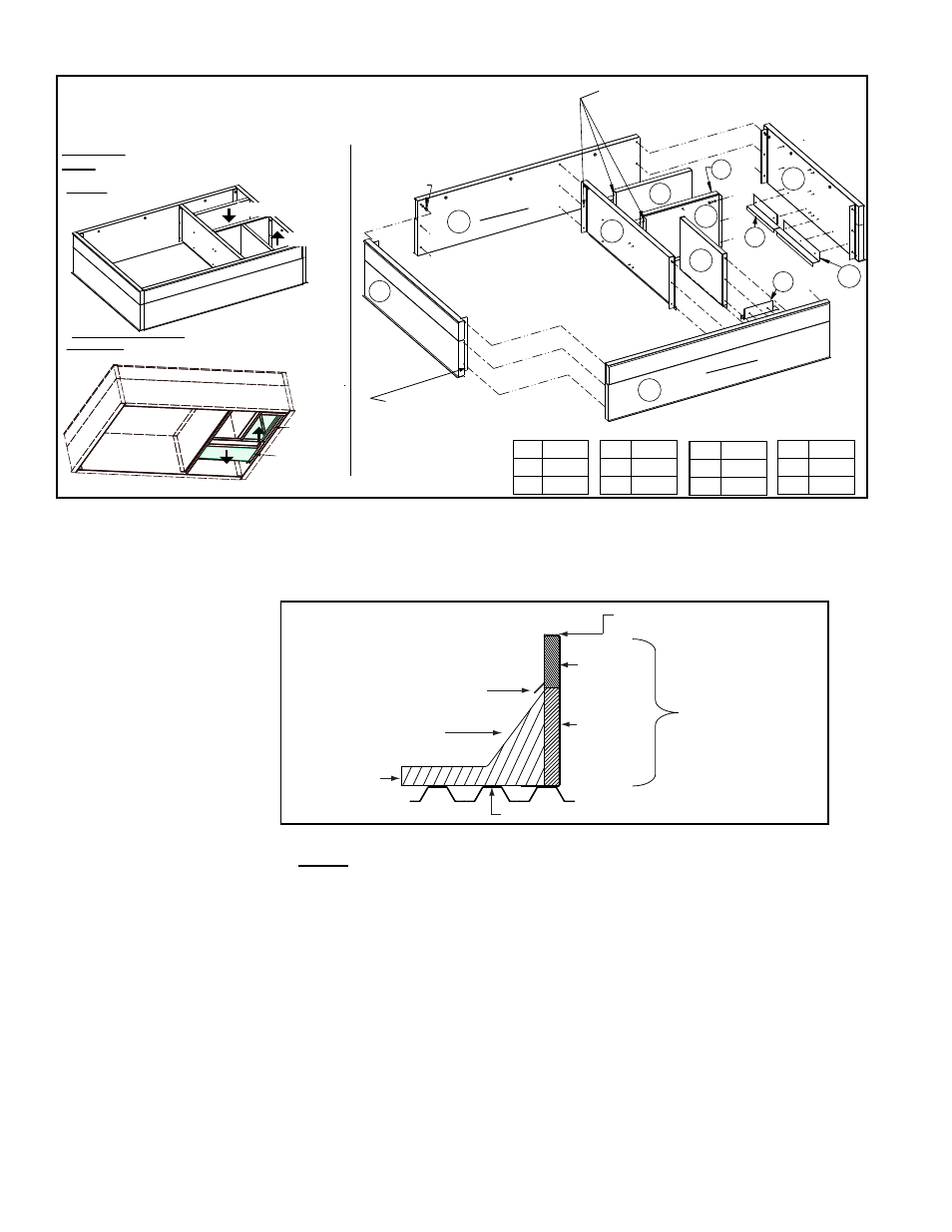
FIGURE 6A - Layout and Assembly of Roof
Curb Components
1
2
3
4
5
6
7
8
9
10
11
(Right End)
(Center
Support)
(Left End)
(Front Side)
(Rear Side)
L
A
J
E
G
C
F
M
B
D
H
K
Use 3/4” Cap Screw, P/N 16247,
with Lockwasher, P/N 1333, and Nut,
P/N 1035, in bottom two holes in each corner.
Use 1-1/4” Lag Screw, P/N 16243,
with Lockwasher, P/N 1333, in all
attachmentsmade into the wood
nailer around the top
of the curb.
Use sheetmetal screws, P/N 11813, for
attaching duct support parts to each
other and to the insulated portion of
the curb rails.
Top View (showing supply
and return airflow)
Assembled
Views
Slide vertical ductwork down from the top
and attach to duct flanges at bottom of curb.
See dimensions on page 9.
Bottom View (from inside the building showing flanges for
ductwork on the openings on the bottom of the curb)
Return Air
Duct Flange
Supply Air
Duct Flange
Return Air
Supply Air
Roofing Felts
(by others)
Cant Strip
(by installer)
Counter Flashing
(by installer)
MUST be sealed between
curb cap and roof curb.
2 x 6
Wood
Nailer
Insulation
Weld, bolt, or lag screw curb to deck structure.
Roof Curb
FIGURE 6B - Cross-
section of Roof Curb
showing Construction
Detail
3.0 Roof Curbs for Z Series Model ZQYRA (cont'd)
6. Install field-supplied flashing.
7.
Before lifting and placing the unit on the curb, check the following:
□
The curb is designed for ductwork to be installed from the top BEFORE the unit
is in place. Slide the ductwork down into the discharge and return air openings.
See dimensions in
FIGURE 6D. Ductwork should be sized slightly smaller with a
minimum 3/4" duct flange that will attach to all sides of the duct connection in the
curb. See the unit installation manual for ductwork requirements.
□
Apply 1/4" x 1-1/4" foam sealant tape to both the top surface of the curb rails and
the top surface of the duct connection supports, being sure to make good butt
joints at all corners. The sealant tape must be applied to the rails to prevent water
leakage into the curb area due to blown rain and capillary action.
□
The unit has field convertible (either vertical or horizontal) supply and return air
opening locations. Depending on whether the ductwork is vertical or horizontal,
verify that the discharge and return air openings being used are uncovered and the
openings not being used are covered.
□
When it is time to lift the unit onto the prepared curb (See Rigging and Lifting,
Installation Form I-ZQYRA), be sure that all of the above preparations have been
made.
4. Check the roof curb for squareness. The curb must be adjusted so that the diagonal measurements are equal
within a tolerance of ±1/8" (3mm).
5. Level the roof curb. To ensure a good weatherproof seal between the cabinet curb cap and the roof curb, the curb
must be leveled in both directions with no twist end to end. Shim as required and secure curb to the roof deck
before installing flashing.
A 260215
B 260216
C 260217
G 259638
H 259639
J 259640
D 260218
E 259636
F 259637
K 259641
L 259642
M 259643
- RCB Option - Installation - Roof Curbs Assembly RDB Option - Installation - Roof Curbs Assembly RDC Option - Installation - Roof Curbs Assembly RDCB Option - Installation - Roof Curbs Assembly RDCC Option - Installation - Roof Curbs Assembly RDDB Option - Installation - Roof Curbs Assembly RCC Option - Installation - Roof Curbs Assembly RDDC Option - Installation - Roof Curbs Assembly RECB Option - Installation - Roof Curbs Assembly RECC Option - Installation - Roof Curbs Assembly REDB Option - Installation - Roof Curbs Assembly REDC Option - Installation - Roof Curbs Assembly RDF Option - Installation - Roof Curbs Assembly RDH Option - Installation - Roof Curbs Assembly REH Option - Installation - Roof Curbs Assembly RHH Option - Installation - Roof Curbs Assembly RXH Option - Installation - Roof Curbs Assembly RPB Option - Installation - Roof Curbs Assembly RPBL Option - Installation - Roof Curbs Assembly RPDBL Option - Installation - Roof Curbs Assembly YDSA Option - Installation - Roof Curbs Assembly YDMA Option - Installation - Roof Curbs Assembly YDHA Option - Installation - Roof Curbs Assembly RBL Option - Installation - Roof Curbs Assembly ADF Option - Installation - Roof Curbs Assembly