Eeprom, 2 eeprom, 3 rtc – Maxim Integrated 71M6533-DB User Manual
Page 51
71M6533-
DB Demo Board User’s Manual
Page: 51 of 75
`
REV 3
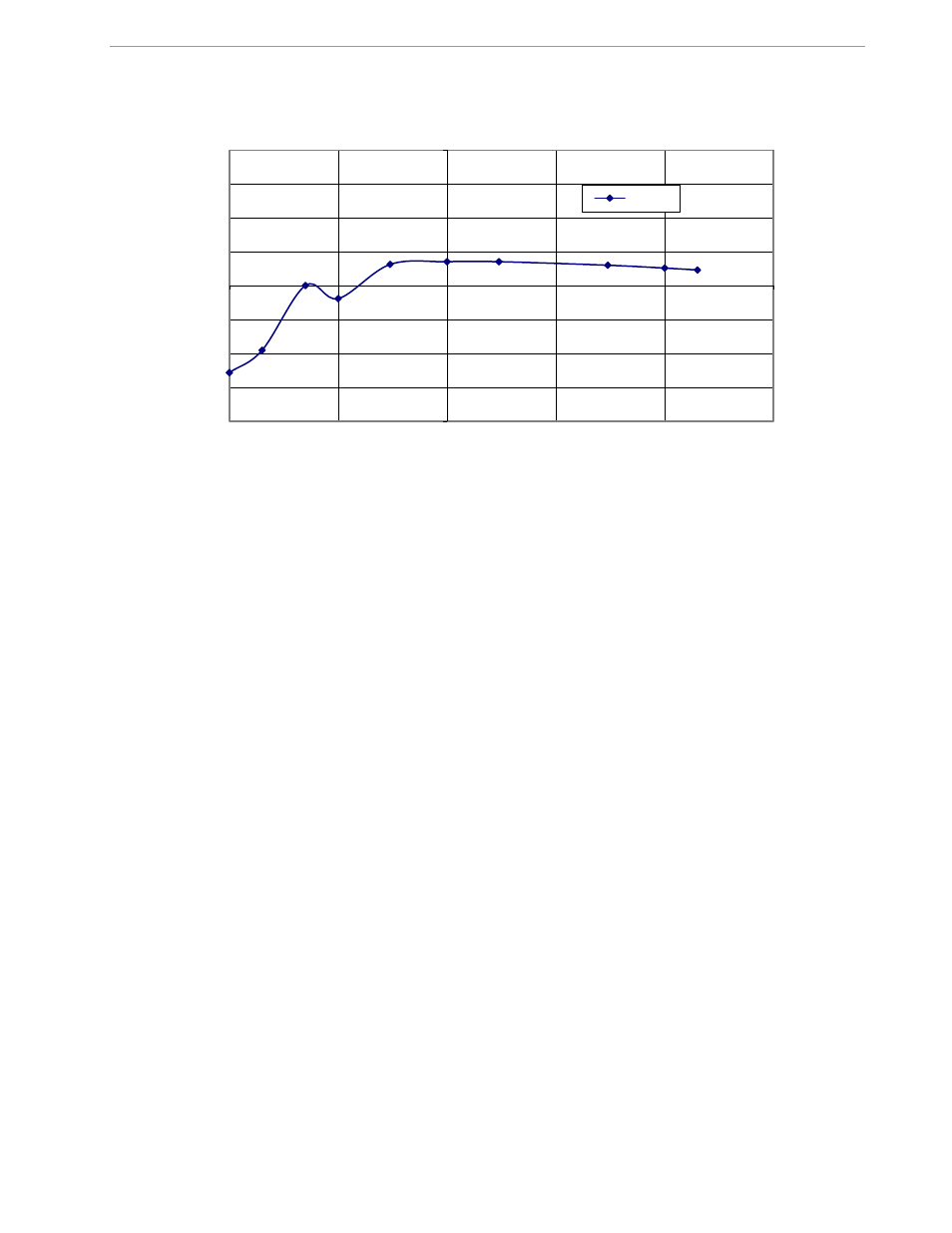
Figure 2-15: Wh Load Line in Differential Mode at Room Temperature
2.5.2 EEPROM
Testing the EEPROM provided on the Demo Board is straightforward and can be done using the serial
command line interface (CLI) of the Demo Code.
To write a string of text characters to the EEPROM and read it back, we apply the following sequence of CLI
commands:
>EEC1
Enables the EEPROM
>EESthis is a test
Writes text to the buffer
>EET80
Writes buffer to address 80
Written to EEPROM address 00000080 74 68 69 73 20 69 73 20 61 ….
Response from Demo Code
>EER80.E
Reads text from the buffer
Read from EEPROM address 00000080 74 68 69 73 20 69 73 20 61 ….
Response from Demo Code
>EEC0
Disables the EEPROM
2.5.3 RTC
Testing the RTC inside the 71M6533 IC is straightforward and can be done using the serial command line
interface (CLI) of the Demo Code.
To set the RTC and check the time and date, we apply the following sequence of CLI commands:
>M10
LCD display to show calendar date
>RTD05.09.27.3
Sets the date to 9/27/2005 (Tuesday)
>M9
LCD display to show time of day
>RTT10.45.00
Sets the time to 10:45:00. AM/PM distinction: 1:22:33PM = 13:22:33
-0.2
-0.15
-0.1
-0.05
0
0.05
0.1
0.15
0.2
0.01
0.1
1
10
100
1000
E
rror
[%
]
I [A]
Load Line in Differential Mode
Error(%)