Power saving measures, Schematic information, Components for the v1 pin – Maxim Integrated 71M6533-DB User Manual
Page 46: Reset circuit, Figure 2-7: voltage divider for v1, Table 2-1: power saving measures, 3 power saving measures, 4 schematic information
71M6533-
DB Demo Board User’s Manual
Page: 46 of 75
`
REV 3
2.3 POWER SAVING MEASURES
In many cases, especially when operating the 71M6533 from a battery, it is desirable to reduce the power
consumed by the chip to a minimum. This can be achieved with the measures listed in Table 2-1.
Power Saving Measure
Software Control
Typical
Savings
Disable the CE
CE_EN
= 0
0.16mA
Disable the ADC
ADC_DIS
= 1
1.8mA
Disable clock test output CKTEST
CKOUTDIS
= 1
0.6mA
Disable emulator clock
ECK_DIS
= 1
0.1mA
Disable RTM outputs
RTM_EN
= 0
0.01mA
Disable SSI output
SSI_EN
= 0
Select DGND for the multiplexer input
TMUX[3:0]
= 0
Disable reference voltage output
VREF_DIS
= 1
Reduce the clock for the MPU
MPU_DIV
= 5
0.4mA
Table 2-1: Power Saving Measures
2.4 SCHEMATIC INFORMATION
In this section, hints on proper schematic design are provided that will help designing circuits that are functional
and sufficiently immune to EMI (electromagnetic interference).
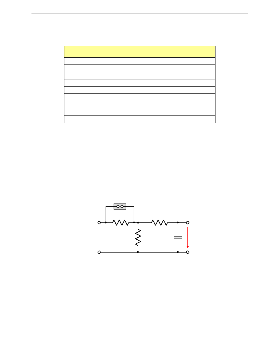
2.4.1 COMPONENTS FOR THE V1 PIN
The V1 pin of the 71M6533 can never be left unconnected.
A voltage divider should be used to establish that V1 is in a safe range when the meter is in mission mode (V1
must be lower than 2.9V in all cases in order to keep the hardware watchdog timer enabled). For proper
debugging or loading code into the 71M6533 mounted on a PCB, it is necessary to have a provision like the
header JP1 shown above R1 in Figure 2-7. A shorting jumper on this header pulls V1 up to V3P3 disabling the
hardware watchdog timer.
Figure 2-7: Voltage Divider for V1
On the 71M6533-DB Demo Board this feature is implemented with resistors R83/R86, capacitor C31 and TP10.
See the board schematics in the Appendix for details.
2.4.2 RESET CIRCUIT
Even though a functional meter will not necessarily need a reset switch, the 71M6533-DB Demo Boards provide
a reset pushbutton that can be used when prototyping and debugging software (see Figure 2-8).. For a
production meter, the RESET pin should be pulled down hard to GNDD.
V3P3
R
2
V1
R
1
R
3
5k
Ω
C
1
100pF
GND
V3P3
R
2
V1
R
1
R
3
5k
Ω
C
1
100pF
GND