Oscillator, Eeprom, Figure 2-8: external components for resetz – Maxim Integrated 71M6533-DB User Manual
Page 47: Figure 2-9: oscillator circuit
71M6533-
DB Demo Board User’s Manual
Page: 47 of 75
`
REV 3
Figure 2-8: External Components for RESETZ
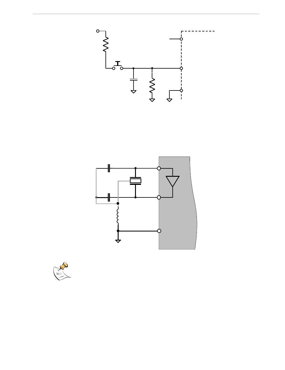
2.4.3 OSCILLATOR
The oscillator of the 71M6533 drives a standard 32.768kHz watch crystal (see Figure 2-9). Crystals of this type
are accurate and do not require a high-current oscillator circuit. The oscillator in the 71M6533 has been
designed specifically to handle watch crystals and is compatible with their high impedance and limited power
handling capability. The oscillator power dissipation is very low to maximize the lifetime of any battery backup
device attached to the VBAT pin.
Figure 2-9: Oscillator Circuit
It is not necessary to place an external resistor across the crystal
For better resistance to EMI, the GND connection for the capacitors should be through a
ferrite bead.
2.4.4 EEPROM
EEPROMs should be connected to the pins DIO4 and DIO5 (see Figure 2-10). These pins can be switched
from regular DIO to implement an I2C interface by setting the I/O RAM register DIO_EEX (0x2008[4]) to 1. Pull-
up resistors of 3k
must be provided for both the SCL and SDA signals.
R
1
RESET
71M6533
DGND
V3P3D
R
2
VBAT/
V3P3D
Reset
Switch
1k
Ω
1nF
10k
Ω
R
1
RESET
71M6533
DGND
V3P3D
R
2
VBAT/
V3P3D
Reset
Switch
1k
Ω
1nF
10k
Ω
XOUT
XIN
TEST
GND
71M6533
Ferrite