Ferrites, Testing the demo board, Functional meter test – Maxim Integrated 71M6533-DB User Manual
Page 49: Figure 2-12: optical interface block diagram, 5 testing the demo board
71M6533-
DB Demo Board User’s Manual
Page: 49 of 75
`
REV 3
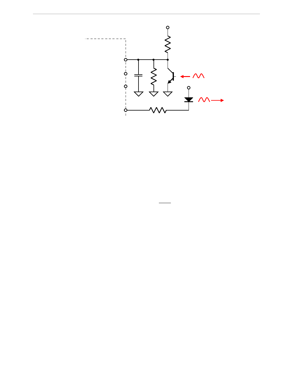
Figure 2-12: Optical Interface Block Diagram
The IR diode should be connected between terminal 2 of header J12 on the Demo Board (cathode) and the
V3P3 voltage (anode), which is accessible at terminal 1 of header J12 (see Figure 3).
J12 on the 71M6533-DB Demo Boards has all the provisions for connecting the IR LED and photo-transistor.
2.4.7 FERRITES
Ferrite beads on the PCB are useful for the rejection of noise and general EMI events such as ESD and EFT.
Some precautions apply:
1) Ferrites should not be placed upstream from MOVs, TVS, and other clamping devices, since large currents
will flow through the ferrites in the event of a surge. If the ferrite is not designed for large surge currents, it
will burn up.
2) Placing ferrite beads directly in series with the ADC inputs of the 71M6533 can cause inaccuracies in Wh
readings over temperature. Ferrites should be placed before the balance resistor and reservoir capacitor.
For details, see Maxim Application Note AN-5292.
2.5 TESTING THE DEMO BOARD
This section will explain how the 71M6533 IC and the peripherals can be tested. Hints given in this section will
help evaluating the features of the Demo Board and understanding the IC and its peripherals.
2.5.1 FUNCTIONAL METER TEST
This is the test that every Demo Board has to pass before being integrated into a Demo Kit. Before going into
the functional meter test, the Demo Board has already passed a series of bench-top tests, but the functional
meter test is the first test that applies realistic high voltages (and current signals from current transformers) to
the Demo Board.
Figure 2-13 shows a meter connected to a typical calibration system. The calibrator supplies calibrated voltage
and current signals to the meter. It should be noted that the current flows through the CT or CTs that are not
part of the Demo Board. The Demo Board rather receives the voltage output signals from the CT. An optical
pickup senses the pulses emitted by the meter and reports them to the calibrator. Some calibration systems
have electrical pickups. The calibrator measures the time between the pulses and compares it to the expected
time, based on the meter Kh and the applied power.
OPT_TX
R
2
R
1
OPT_RX
71M6533
V3P3SYS
Phototransistor
LED
10k
Ω
100pF
V3P3SYS
OPT_TX
R
2
R
1
OPT_RX
71M6533
V3P3SYS
Phototransistor
LED
10k
Ω
100pF
OPT_TX
R
2
R
1
OPT_RX
71M6533
V3P3SYS
Phototransistor
LED
10k
Ω
100pF
OPT_TX
R
2
R
1
OPT_RX
71M6533
V3P3SYS
Phototransistor
LED
10k
Ω
100pF
V3P3SYS