Calibration procedure with three measurements, Figure 2-2: phase angle definitions, 1 calibration procedure with three measurements – Maxim Integrated 71M6533-DB User Manual
Page 39
71M6533-
DB Demo Board User’s Manual
Page: 39 of 75
`
REV 3
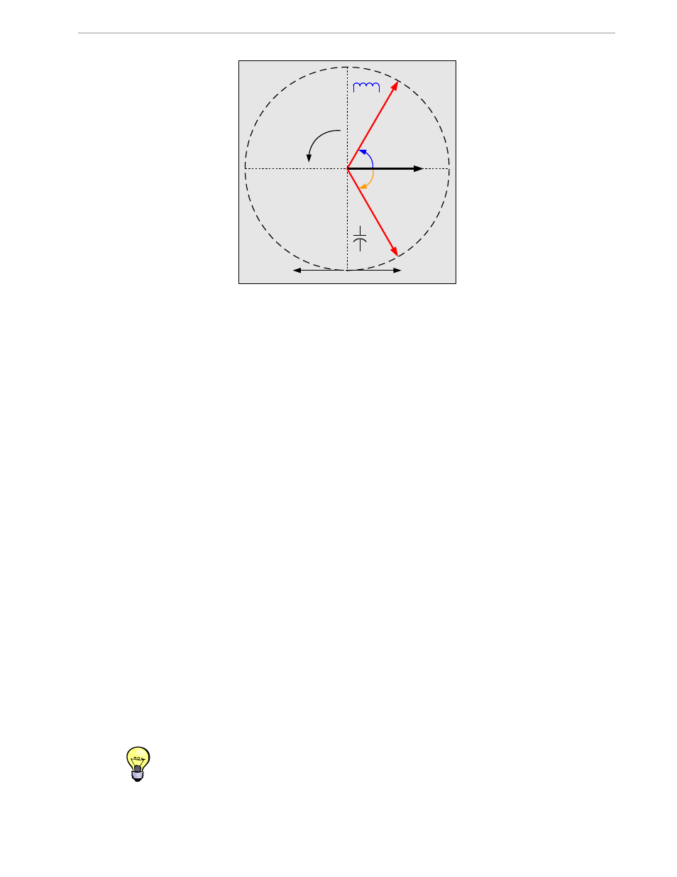
Figure 2-2: Phase Angle Definitions
The calibration procedures described below should be followed after interfacing the voltage and current sensors
to the 71M6533 chip. When properly interfaced, the V3P3 power supply is connected to the meter neutral and is
the DC reference for each input. Each voltage and current waveform, as seen by the 71M6533, is scaled to be
less than 250mV (peak).
2.2.1 CALIBRATION PROCEDURE WITH THREE MEASUREMENTS
Each phase is calibrated individually. The calibration procedure is as follows:
1) The calibration factors for all phases are reset to their default values, i.e.
CAL_In
=
CAL_Vn
= 16384,
and
PHADJ_n
= 0.
2) An RMS voltage V
ideal
consistent with the meter’s nominal voltage is applied, and the RMS reading
V
actual
of the meter is recorded. The voltage reading error Axv is determined as
Axv = (V
actual -
V
ideal
) / V
ideal
3) Apply the nominal load current at phase angles 0° and 60°, measure the Wh energy and record the
errors E
0
AND E
60
.
4) Calculate the new calibration factors
CAL_In
,
CAL_Vn,
and
PHADJ_n
, using the formulae presented
in section 2.1.1 or using the spreadsheet presented in section 2.2.4.
5) Apply the new calibration factors
CAL_In
,
CAL_Vn
, and
PHADJ_n
to the meter. The memory
locations for these factors are given in section 1.9.1.
6) Test the meter at nominal current and, if desired, at lower and higher currents and various phase
angles to confirm the desired accuracy.
7) Store the new calibration factors
CAL_In
,
CAL_Vn
, and
PHADJ_n
in the EEPROM memory of the
meter. If the calibration is performed on a
Maxim’s Teridian Demo Board, the methods involving the
command line interface, as shown in sections 1.9.3 and 1.9.4, can be used.
8) Repeat the steps 1 through 7 for each phase.
9) For added temperature compensation, read the value
TEMP_RAW
(CE RAM) and write it to
TEMP_NOM
(CE RAM). If Demo Code 4.6n or later is used, this will automatically calculate the
correction coefficients PPMC and PPMC2 from the nominal temperature and from the characterization
data contained in the on-chip fuses.
Tip: Step 2 and the energy measurement at 0° of step 3 can be combined into one step.
Voltage
Current
+60°
Using Energy
Generating Energy
Current lags
voltage
(inductive
)
Current leads
voltage
(capacitive
)
-60°
Voltage
Positive
direction