Optical interface, Figure 2-10: eeprom circuit, Figure 2-11: lcd connections – Maxim Integrated 71M6533-DB User Manual
Page 48
71M6533-
DB Demo Board User’s Manual
Page: 48 of 75
`
REV 3
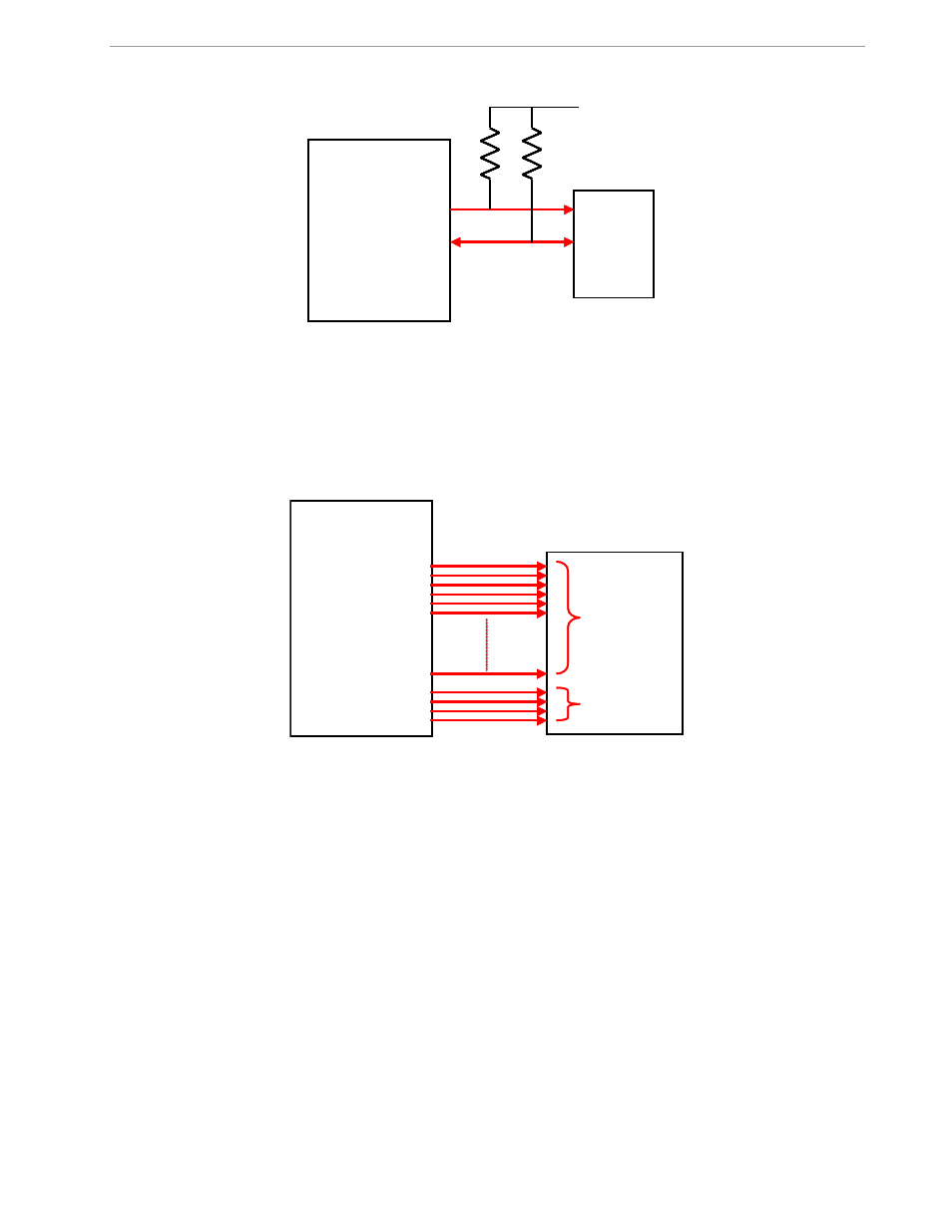
Figure 2-10: EEPROM Circuit
2.4.5 LCD
The 71M6533 has an on-chip LCD controller capable of controlling static or multiplexed LCDs. Figure 2-11
shows the basic connection for LCDs. Note that the LCD module itself has no power connection.
Figure 2-11: LCD Connections
2.4.6 OPTICAL INTERFACE
The 71M6533 IC is equipped with two pins supporting the optical interface: OPT_TX and OPT_RX. The
OPT_TX pin can be used to drive a visual or IR light LED with up to 20mA, a series resistor (R
2
helps limiting the current). The OPT_RX pin can be connected to the collector of a photo-transistor, as shown in
Figure 2-12.
DIO4
DIO5
71M6533
EEPROM
SCL
SDA
V3P3D
10k
Ω
10k
Ω
DIO4
DIO5
71M6533
EEPROM
SCL
SDA
V3P3D
10k
Ω
10k
Ω
segments
71M6533
LCD
commons
segments
71M6533
LCD
commons
- DS80C390 (58 pages)
- DS5001FP (26 pages)
- MAX1416 (14 pages)
- MAX5865 (18 pages)
- DS33Z41 (167 pages)
- MAX1202 (7 pages)
- USBTO232 (31 pages)
- HFAN-09.5.0: Pattern Creator/Converter Software (8 pages)
- MAX-IDE MAXQ Microcontrollers (11 pages)
- MAX6876 Power-Supply Tracker/Sequencer (6 pages)
- MAX6877 Power-Supply Tracker/Sequencer (3 pages)
- 78Q8430 ARM9(920T) Linux Driver Diagnostic Guide (19 pages)
- 78Q8430 Software Driver (54 pages)
- 78Q8430 ST 5100/OS-20 with NexGen TCP/IP Stack (28 pages)
- 6612_OMU_S2_URT_V1_13 (56 pages)
- 6612_OMU_S2+2_URT_V1_14 (58 pages)
- 71M6511 Power Meter IC Family Software (137 pages)
- 71M65xx ADM51 ICE Safety Notice (2 pages)
- 71M6511 2-Layer Demo Board (2 pages)
- 71M6511 4-Layer Demo Board (2 pages)
- 78Q8430 Linux Driver ARM Platform (22 pages)
- 71M6513 Demo Board (2 pages)
- 71M6521DE Energy Meter IC Family Software (138 pages)
- 71M6521 Demo Board (2 pages)
- 71M6531 Demo Board (2 pages)
- 71M6531 Energy Meter IC Family Software (116 pages)
- 71M6533 Demo Board (2 pages)
- 71M6534H Demo Board (2 pages)
- 71M6515H Demo Board (2 pages)
- 73S1209F Evaluation Board (2 pages)
- 73S12xxF (38 pages)
- 73S12xxF Software (93 pages)
- 73S1210F Evaluation Board Lite (2 pages)
- 73S1210F Evaluation Board (2 pages)
- 73S1210F Multi-SAM Evaluation Board Lite (2 pages)
- 73S12xxF USB-CCID Linux DFU Host Application (8 pages)
- 73S1215F Device Firmware Upgrade Host Driver/Application (10 pages)
- 73S12xxF USB-CCID Host GUI (22 pages)
- 73S1215F Windows XP 32 USB CCID and DFU Drivers (15 pages)
- 73S1215F CCID USB Linux Driver (16 pages)
- 73S1215F Evaluation Board (2 pages)
- 73S1215F Evaluation Board Lite (2 pages)
- 73S1217F Evaluation Board (2 pages)
- 73S1217F Evaluation Board Lite (2 pages)
- MAXQ Family (216 pages)