The programming interface of the 71m6533, Demo code, Demo code description – Maxim Integrated 71M6533-DB User Manual
Page 27: Important demo code mpu parameters, Table 1-3: flash programming interface signals, 10 demo code, 1 demo code description, 2 important demo code mpu parameters
71M6533-
DB Demo Board User’s Manual
Page: 27 of 75
`
REV 3
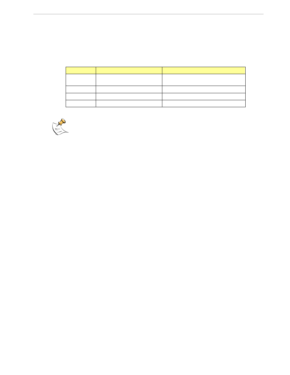
1.9.7 THE PROGRAMMING INTERFACE OF THE 71M6533
Flash Downloader/ICE Interface Signals
The signals listed in Table 1-3 are necessary for communication between the Flash Downloader or ICE and the
71M6533.
Signal
Direction
Function
ICE_E
Input to the 71M6533
ICE interface is enabled when ICE_E is
pulled high
E_TCLK
Output from 71M6533
Data clock
E_RXTX
Bi-directional
Data input/output
E_RST
Bi-directional
Flash Downloader Reset (active low)
Table 1-3: Flash Programming Interface Signals
The E_RST signal should only be driven by the Flash Downloader when enabling these interface
signals. The Flash Downloader must release E_RST at all other times.
1.10 DEMO CODE
1.10.1 DEMO CODE DESCRIPTION
The Demo Board is shipped preloaded with Demo Code revision 4.4.16 or later in the 71M6533 or 71M6533H
chip. The code revision can easily be verified by entering the command >i via the serial interface (see section
1.8.1). Check with your local MAXIM INTEGRADED PRODUCTS representative or FAE for the latest revision.
The Demo Code offers the following features:
It provides basic metering functions such as pulse generation, display of accumulated energy,
frequency, date/time, and enables the user to evaluate the parameters of the metering IC such as
accuracy, harmonic performance, etc.
It maintains and provides access to basic household functions such as real-time clock (RTC).
It provides access to control and display functions via the serial interface, enabling the user to view
and modify a variety of meter parameters such as Kh, calibration coefficients, temperature
compensation etc.
It provides libraries for access of low-level IC functions to serve as building blocks for code
development.
A detailed description of the Demo Code can be found in the Software User’s Guide (SUG). In addition, the
comments contained in the library provided with the Demo Kit can serve as useful documentation.
The Software User’s Guide contains the following information:
Design guide
Design reference for routines
Tool Installation Guide
List of library functions
80515 MPU Reference (hardware, instruction set, memory, registers)
1.10.2 IMPORTANT DEMO CODE MPU PARAMETERS
In the Demo Code, certain MPU XRAM parameters have been given fixed addresses in order to permit easy
external access. These variables can be read via the serial interface, as described in section 1.7.1, with the )n$
command and written with the )n=xx command where n is the word address. Note that accumulation variables