Compensating for non-linearities, 5 compensating for non-linearities – Maxim Integrated 71M6533-DB User Manual
Page 45
71M6533-
DB Demo Board User’s Manual
Page: 45 of 75
`
REV 3
2.2.5 COMPENSATING FOR NON-LINEARITIES
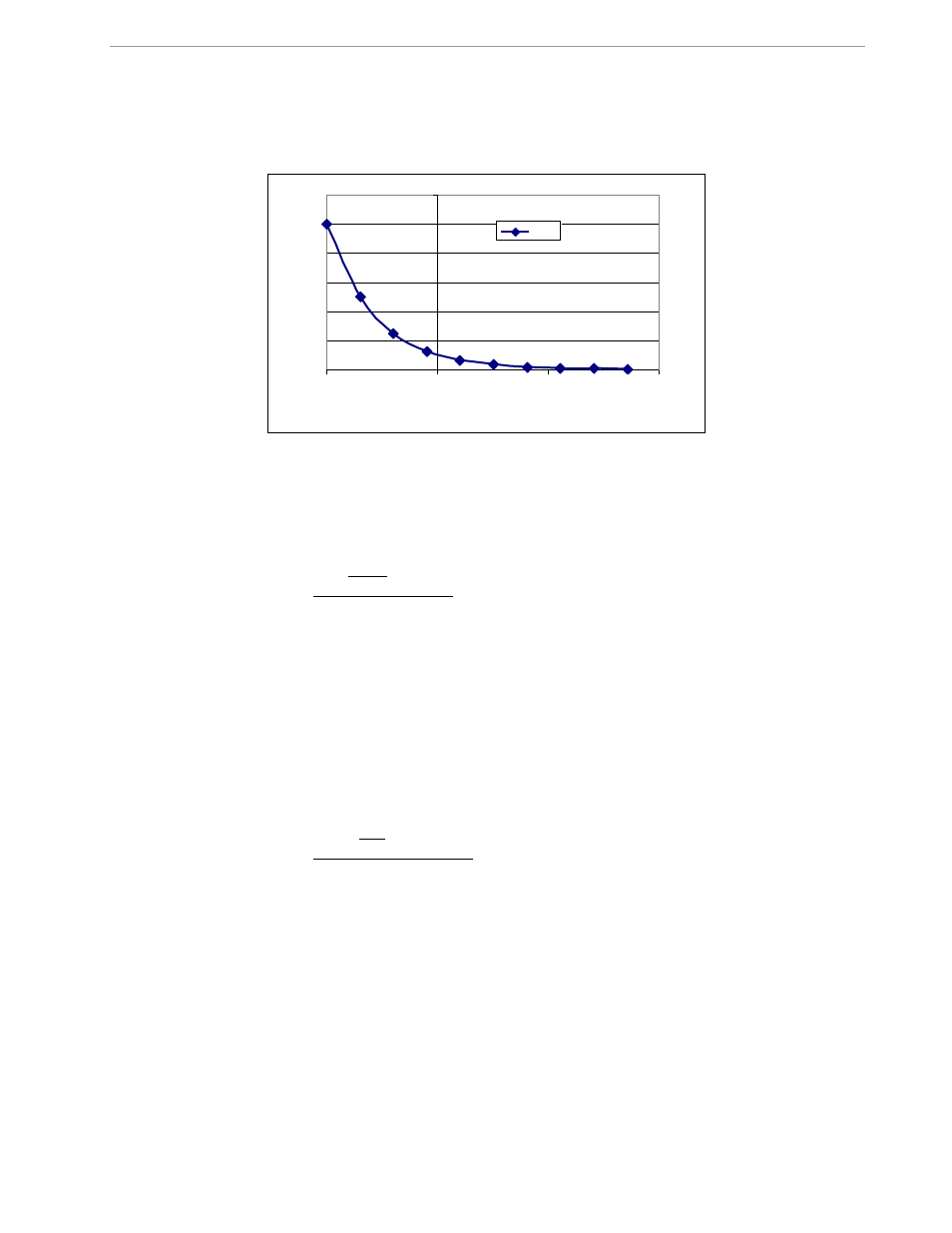
Nonlinearity is most noticeable at low currents, as shown in Figure 2-6, and can result from input noise and
truncation. Nonlinearities can be eliminated using the QUANT variable.
Figure 2-6: Non-Linearity Caused by Quantification Noise
The error can be seen as the presence of a virtual constant noise current. While 10mA hardly contribute any
error at currents of 10A and above, the noise becomes dominant at small currents.
The value to be used for QUANT can be determined by the following formula:
LSB
IMAX
VMAX
I
V
error
QUANT
100
Where error = observed error at a given voltage (V) and current (I),
VMAX = voltage scaling factor, as described in section 1.8.3,
IMAX = current scaling factor, as described in section 1.8.3,
LSB = QUANT LSB value = 1.04173*10
-9
W
Note: The LSB value for QUANT will depend on the CE code that is used for the application. Check the CE code
specification for the actual LSB value.
Example: Assuming an observed error as in Figure 2-6, we determine the error at 1A to be +1%. If VMAX is
600V, IMAX = 208A, QUANT LSB = 7.4162*10
-10
, and if the measurement was taken at 240V, we determine
QUANT as follows:
11339
10
4162
.
7
208
600
1
240
100
1
10
QUANT
QUANT is to be written to the CE location given in the data sheet or in the CE code specification. It does not
matter which current value is chosen as long as the corresponding error value is significant (5% error at 0.2A
used in the above equation will produce the same result for QUANT).
Input noise and truncation can cause similar errors in the VAR calculation that can be eliminated using the
QUANT_VAR variable. QUANT_VAR is determined using the same formula as QUANT.
0
2
4
6
8
10
12
0.1
1
10
100
I [A]
e
rr
o
r
[%
]
error