Figure 2-3 – Maxim Integrated 71M6533-DB User Manual
Page 42
71M6533-
DB Demo Board User’s Manual
Page: 42 of 75
`
REV 3
A spreadsheet is also available for Rogowski coil calibration (see Figure 2-5). Data entry is as follows:
1. All nominal values are entered in the fields of step one.
2. The applied voltage is entered in the y
ellow field labeled “Input Voltage Applied” of step 2. The
entered value will automatically show in the green fields of the two other channels.
3. After measuring the voltages displayed by the meter, these are entered in the yellow fields labeled
“Measured Voltage”. The spreadsheet will show the calculated calibration factors for voltage in the
green fields labeled “CAL_Vx”.
4. The default values (-3973) for PHADJ_x are entered in the yellow fields of step 3. If the calibration
factors for the current are not at
default, their values are entered in the fields labeled “Old CAL_Ix”.
5. The errors of the energy measurements at 0°, 60°, -60°, and 180° are entered in the yellow fields
labeled “% Error …”. The spreadsheet will then display phase error, the current calibration factor
and the PHADJ_x factor in the green fields, one for each phase.
6. If a crosstalk measurement is necessary, it should be performed at a low current, where the
effects of crosstalk are noticeable. First, if (old) values for VFEEDx exist in the meter, they are
entered in the spreadsheet in the row labeled “Old VFEEDx”, one for each phase. If these factors
are zero, “0” is entered for each phase.
7. Test current and test voltage are entered in the yellow fields labeled VRMS and IRMS.
8. The crosstalk measurement is now conducted at a low current with phase angles of 0° and 180°,
and the percentage errors are entered in the yellow fields labeled “% error, 0 deg” and “% error,
180 deg”, one pair of values for each phase. The resulting VFEEDx factors are then displayed in
the green fields labeled VFEEDx.
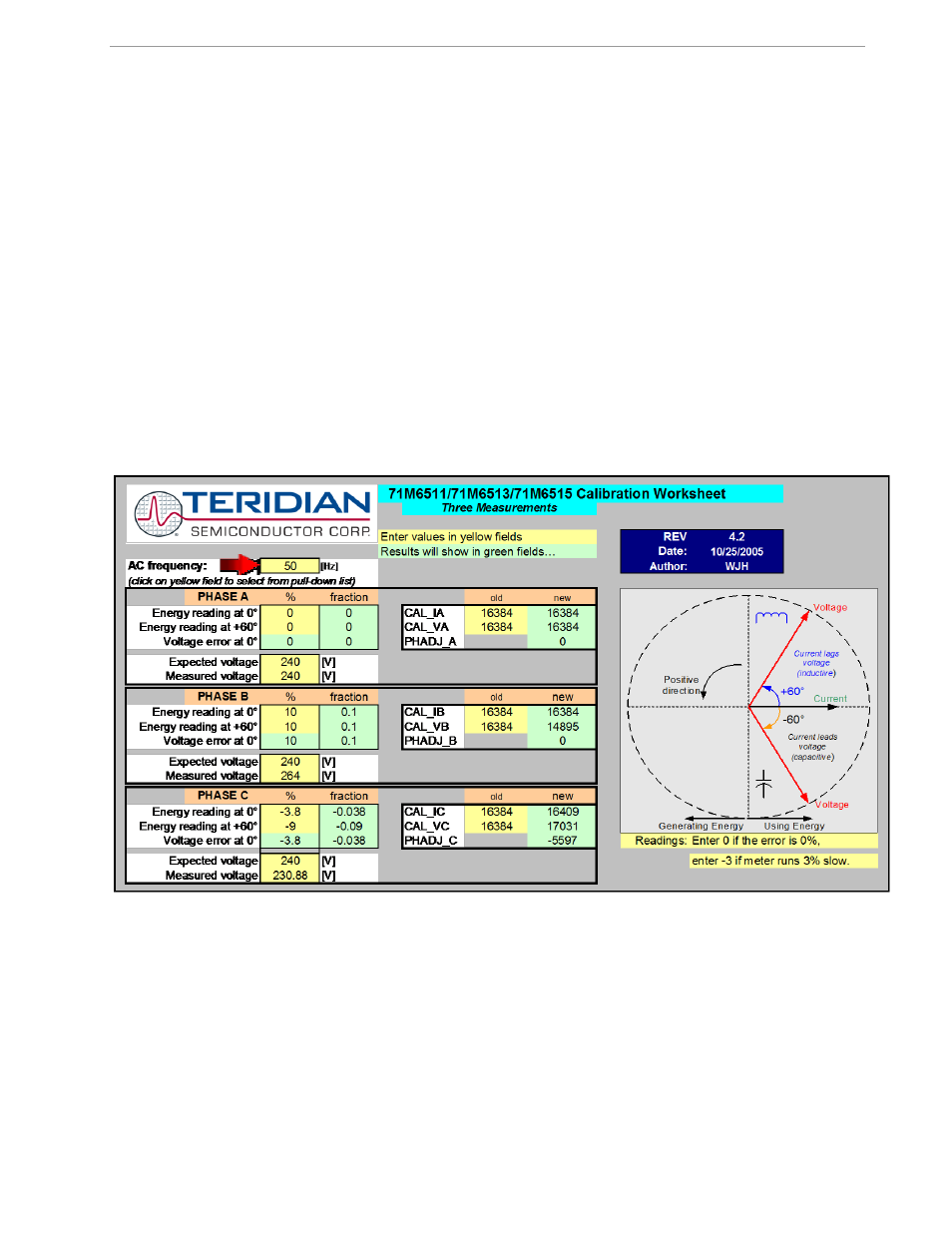
Figure 2-3: Calibration Spreadsheet for Three Measurements