2i0sqsum lsb, Var w, 2v0sqsum lsb – Maxim Integrated 71M6533-DB User Manual
Page 28
71M6533-
DB Demo Board User’s Manual
Page: 28 of 75
`
REV 3
are 64 bits long and are accessed with )n$$ (read) and )n=hh=ll (write) in the case of accumulation variables.
Default values are the values assigned by the Demo Code on start-up.
All MPU Input Parameters are loaded by the MPU at startup and should not need adjustment during meter
calibration.
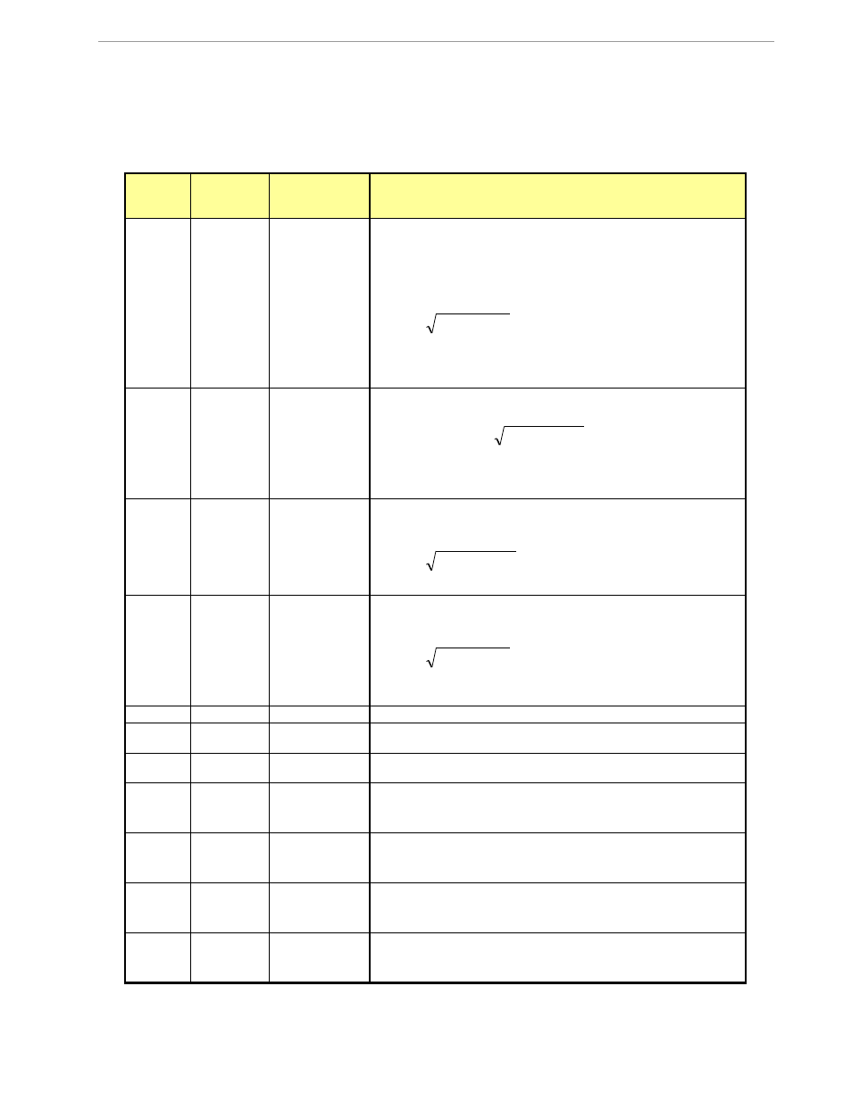
MPU Input Parameters for Metering
XRAM
Word
Address
Default
Value
Name
Description
0x00
433199
ITHRSHLDA
For each element, if WSUM_X or VARSUM_X of that element ex-
ceeds WCREEP_THR, the sample values for that element are not
zeroed. Otherwise, the accumulators for Wh, VARh, and VAh are
not updated and the instantaneous value of IRMS for that
element is zeroed.
16
2
I0SQSUM
LSB
The default value is equivalent to 0.08A. Setting
ITHRSHLDA
to
zero disables creep control.
0x01
0
CONFIG
Bit 0: Sets VA calculation mode.
0: V
RMS
*A
RMS
1:
2
2
VAR
W
Bit 1: Clears accumulators for Wh, VARh, and VAh. This bit
need not be reset.
0x02
764569660
PK_VTHR
When the voltage exceeds this value, bit 5 in the MPU status
word is set, and the MPU might choose to log a warning. Event
logs are not implemented in Demo Code.
16
2
V0SQSUM
LSB
The default value is equivalent to 20% above 240Vrms.
0x03
275652520
PK_ITHR
When the current exceeds this value, bit 6 in the MPU status
word is set, and the MPU might choose to log a warning. Event
logs are not implemented in Demo Code.
16
2
I0SQSUM
LSB
The default value is equivalent to 20% above 30A
RMS
.
0x04
0
Y_CAL_DEG0
RTC adjust, 100ppb. Read only at reset in demo code.
0x05
0
Y_CAL_DEG1
RTC adjust, linear by temperature, 1
0ppb*ΔT, in 0.1˚C. Provided
for optional code.
0x06
0
Y_CAL_DEG2
RTC adjust, squared by temperature, 1ppb*ΔT
2
, in 0.1˚C.
Provided for optional code.
0x07
0
PULSEW_SRC
This address contains a number that points to the selected pulse
source for the Wh output. Selectable pulse sources are listed in
Table 1-5.
0x08
4
PULSER_SRC
This address contains a number that points to the selected pulse
source for the VARh output. Selectable pulse sources are listed
in Table 1-5.
0x09
6000
VMAX
The nominal external RMS voltage that corresponds to 250mV
peak at the ADC input. The meter uses this value to convert
internal quantities to external. LSB=0.1V
0x0A
2080
IMAX
The nominal external RMS current that corresponds to 250mV
peak at the ADC input for channel A. The meter uses this value
to convert internal quantities to external. LSB=0.1A