Calibration parameters, General calibration procedure, 9 calibration parameters – Maxim Integrated 71M6533-DB User Manual
Page 23: 1 general calibration procedure
71M6533-
DB Demo Board User’s Manual
Page: 23 of 75
`
REV 3
1.9 CALIBRATION PARAMETERS
1.9.1 GENERAL CALIBRATION PROCEDURE
Any calibration method can be used with the 71M6533 chips. This Demo Board User’s Manual presents
calibration methods with three or five measurements as recommended methods, because they work with most
manual calibration systems based on counting "pulses" (emitted by LEDs on the meter).
Naturally, a meter in mass production will be equipped with special calibration code offering capabilities beyond
those of the Demo Code. It is basically possible to calibrate using voltage and current readings, with or without
pulses involved. For this purpose, the MPU Demo Code can be modified to display averaged voltage and
current values (as opposed to momentary values). Also, automated calibration equipment can communicate
with the Demo Boards via the serial interface and extract voltage and current readings. This is possible even
with the unmodified Demo Code.
Complete calibration procedures are given in section 2.2 of this manual.
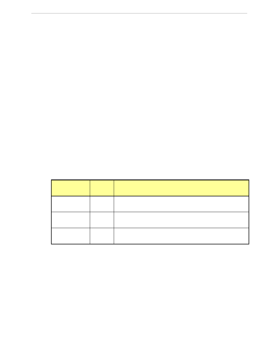
Regardless of the calibration procedure used, parameters (calibration factors) will result that will have to be
applied to the 71M6533 chip in order to make the chip apply the modified gains and phase shifts necessary for
accurate operation. Table 1-2 shows the names of the calibration factors, their function, and their location in the
CE RAM.
Again, the command line interface can be used to store the calibration factors in their respective CE RAM
addresses. For example, the command
>]10=+16302
stores the decimal value 16302 in the CE RAM location controlling the gain of the current channel (CAL_IA) for
phase A.
The command
>]11=4005
stores the hexadecimal value 0x4005 (decimal 16389) in the CE RAM location controlling the gain of the
voltage channel for phase A (
CAL_VA
).
Constant
CE
Address
(hex)
Description
CAL_VA
CAL_VB
CAL_VC
0x11
0x13
0x15
Adjusts the gain of the voltage channels. +16384 is the typical value. The
gain is directly proportional to the CAL parameter. Allowed range is 0 to
32767. If the gain is 1% slow, CAL should be increased by 1%.
CAL_IA
CAL_IB
CAL_IC
0x10
0x12
0x14
Adjusts the gain of the current channels. +16384 is the typical value. The
gain is directly proportional to the CAL parameter. Allowed range is 0 to
32767. If the gain is 1% slow, CAL should be increased by 1%.
PHADJ_A
PHADJ_B
PHADJ_C
0x18
0x19
0x1A
This constant controls the CT phase compensation. No compensation
occurs when PHADJ=0. As PHADJ is increased, more compensation is
introduced.
Table 1-2: CE RAM Locations for Calibration Constants