Figure 2-13: meter with calibration system, Figure 2-14: calibration system screen – Maxim Integrated 71M6533-DB User Manual
Page 50
71M6533-
DB Demo Board User’s Manual
Page: 50 of 75
`
REV 3
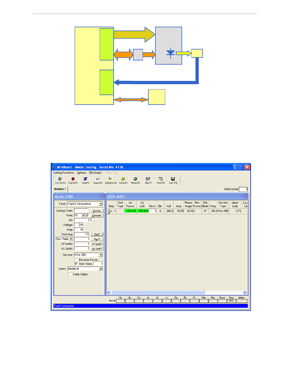
Figure 2-13: Meter with Calibration System
Maxim’s Teridian Demo Boards are not calibrated prior to shipping. However, the Demo Board pulse outputs
are tested and compared to the expected pulse output rate. Figure 2-14 shows the screen on the controlling PC
for a typical Demo Board. The error numbers are given in percent. This means that for the measured Demo
Board, the sum of all errors resulting from tolerances of PCB components, CTs, and 71M6533 tolerances was
–
3.41%, a range that can easily be compensated by calibration.
Figure 2-15 shows a load-line obtained with a 6533 in differential mode. As can be seen, dynamic ranges of
10,000:1 for current can be achieved with good circuit design, layout, cabling, and, of course, good current
sensors.
Figure 2-14: Calibration System Screen
Calibrator
AC Voltage
Current CT
Meter
under
Test
Optical Pickup
for Pulses
C
a
li
b
ra
te
d
O
u
tp
u
ts
Pu
ls
e
C
o
u
n
te
r
PC
- DS80C390 (58 pages)
- DS5001FP (26 pages)
- MAX1416 (14 pages)
- MAX5865 (18 pages)
- DS33Z41 (167 pages)
- MAX1202 (7 pages)
- USBTO232 (31 pages)
- HFAN-09.5.0: Pattern Creator/Converter Software (8 pages)
- MAX-IDE MAXQ Microcontrollers (11 pages)
- MAX6876 Power-Supply Tracker/Sequencer (6 pages)
- MAX6877 Power-Supply Tracker/Sequencer (3 pages)
- 78Q8430 ARM9(920T) Linux Driver Diagnostic Guide (19 pages)
- 78Q8430 Software Driver (54 pages)
- 78Q8430 ST 5100/OS-20 with NexGen TCP/IP Stack (28 pages)
- 6612_OMU_S2_URT_V1_13 (56 pages)
- 6612_OMU_S2+2_URT_V1_14 (58 pages)
- 71M6511 Power Meter IC Family Software (137 pages)
- 71M65xx ADM51 ICE Safety Notice (2 pages)
- 71M6511 2-Layer Demo Board (2 pages)
- 71M6511 4-Layer Demo Board (2 pages)
- 78Q8430 Linux Driver ARM Platform (22 pages)
- 71M6513 Demo Board (2 pages)
- 71M6521DE Energy Meter IC Family Software (138 pages)
- 71M6521 Demo Board (2 pages)
- 71M6531 Demo Board (2 pages)
- 71M6531 Energy Meter IC Family Software (116 pages)
- 71M6533 Demo Board (2 pages)
- 71M6534H Demo Board (2 pages)
- 71M6515H Demo Board (2 pages)
- 73S1209F Evaluation Board (2 pages)
- 73S12xxF (38 pages)
- 73S12xxF Software (93 pages)
- 73S1210F Evaluation Board Lite (2 pages)
- 73S1210F Evaluation Board (2 pages)
- 73S1210F Multi-SAM Evaluation Board Lite (2 pages)
- 73S12xxF USB-CCID Linux DFU Host Application (8 pages)
- 73S1215F Device Firmware Upgrade Host Driver/Application (10 pages)
- 73S12xxF USB-CCID Host GUI (22 pages)
- 73S1215F Windows XP 32 USB CCID and DFU Drivers (15 pages)
- 73S1215F CCID USB Linux Driver (16 pages)
- 73S1215F Evaluation Board (2 pages)
- 73S1215F Evaluation Board Lite (2 pages)
- 73S1217F Evaluation Board (2 pages)
- 73S1217F Evaluation Board Lite (2 pages)
- MAXQ Family (216 pages)