EVCO EPH4EXP Hardware manual User Manual
Page 37
EVCO S.p.A.
c-pro 3 | Hardware manual ver. 3.2 | Codice 114CP3E324
page 37 of 116
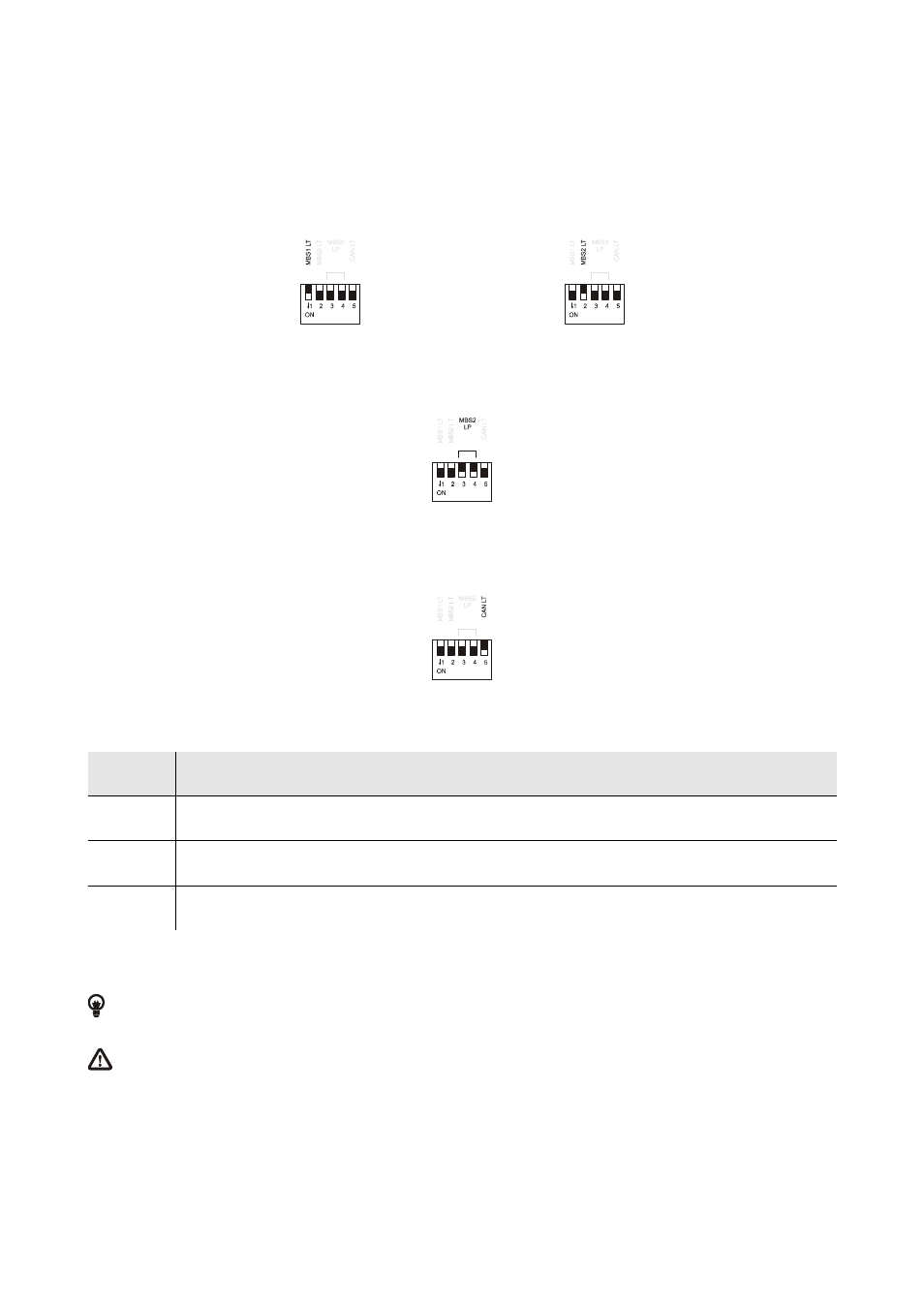
MICRO-SWITCH
Micro-switch to:
-
plug in the terminations of the RS-485 ports (120
Ω
, 0.25 W); position micro-switch 1 on position ON to plug in the termination
of the first RS-485 port and micro-switch 2 on position ON to plug in the termination of the second RS-485 port (plug in the
termination of the first and of the last element of the network)
-
polarize the network of the second RS-485 port (560
Ω
, 0.25 W); position micro-switches 3 and 4 on position ON to polarize
the network of the second RS-485 port (the network must be polarized by an element of the network same).
-
plug in the termination of the first CAN port (120
Ω
, 0.5 W); position micro-switch 4 on position ON to plug in the termination of
the CAN port (plug in the termination of the first and of the last element of the network).
CAN BUS
First CAN port.
Terminal
Meaning
CAN +
signal +
CAN -
signal -
GND
ground
The maximum number of devices that can make a CAN network (32) depends on the bus load; the bus load depends on the baud rate
of the CANbus communication and on the kind of device in the network.
For example: a CAN network can be made of a programmable controller, of four I / O expansions and of four user interfaces
with baud rate 500,000 baud.
The maximum length of the connecting cables of the CAN port depends on the baud rate of the CANbus communication, as
follows:
-
1,000 m (3,280 ft) with baud rate 20,000 baud
-
500 m (1,640 ft) with baud rate 50,000 baud
-
250 m (820 ft) with baud rate 125,000 baud
-
50 m (164 ft) with baud rate 500,000 baud.
Connect the CAN port using a twisted pair.