2 description of the control module – EVCO EVCSR338J9 User Manual
Page 14
EVCO S.p.A.
Vcolor 338 S | Installer manual ver. 1.2 | Code 144VC338SE124
page 14 of 50
For further information, see the next chapters.
4.2
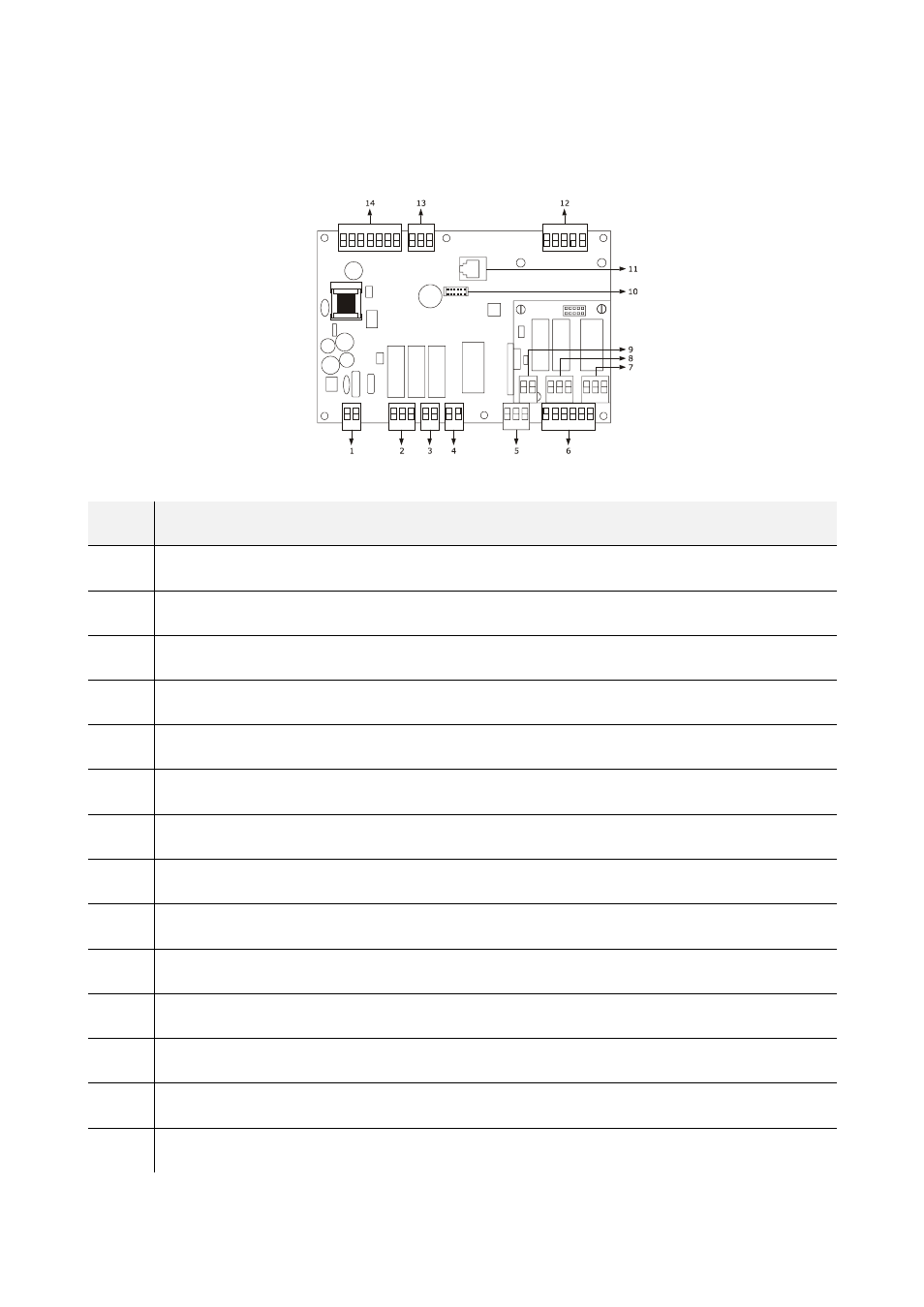
Description of the control module
The following drawing illustrates the aspect of the device's control module.
The following table illustrates the meaning of device's control module parts.
PART
MEANING
1 power
supply
2
digital outputs K3 and K4
3
digital output K5
4
digital output K1
5
digital output K2
6
digital inputs for potential-free contact
7 K8
digital
output
8
digital inputs K6 and K7
9
digital input for high voltage contact
10 reserved
11 reserved
12 analogue
inputs
13 analogue
output
14
RS-485 MODBUS port and communication port with user interface
For further information, see the next chapters.
- EV3B22N7 (2 pages)
- EV3B23N7 (2 pages)
- EV3B31N7 (2 pages)
- EV3X21N7 (2 pages)
- EVK203N7 (2 pages)
- EVK204N9 (5 pages)
- EVK214N9 (6 pages)
- EVX201N7 (8 pages)
- EVX225N7 (6 pages)
- EVXS214N9 (8 pages)
- EVXV201N7 (9 pages)
- EVR202N7 (10 pages)
- EVRS204N9 (8 pages)
- EVRS225N9 (10 pages)
- TM102A (2 pages)
- EVK404N9 (8 pages)
- EPD4BF3 (2 pages)
- EPD4BF3 (70 pages)
- EV6223P7 (2 pages)
- EVB1226N9XXC (92 pages)
- EVB1214N9 (88 pages)
- EVRSF204N9VRB (8 pages)
- EVF204N9 (8 pages)
- EVF205N9 (8 pages)
- EVF214N9 (8 pages)
- EVF215N9 (8 pages)
- EK820AP7 (4 pages)
- EK825AP7 (14 pages)
- EVCSR818P9EF (94 pages)
- EVF815P9 (2 pages)
- EVF815P9 (60 pages)
- EVF818P9 (2 pages)
- EVF818P9 (76 pages)
- EVX802P7 Installer manual (66 pages)
- EVX802P7 Installer manual (2 pages)
- EVXS815P9 Installer manual (2 pages)
- EVXS815P9 Installer manual (60 pages)
- EVXV802P7 Installer manual (2 pages)
- EVXV802P7 Installer manual (66 pages)
- EVK802P7 (2 pages)
- EVFTFT818P7U (2 pages)
- EVFTFT818P7U Installer manual (94 pages)
- EV7601J6 (2 pages)
- EV9303J9 (2 pages)
- EV9313J9 (2 pages)