Rs232 wiring at the bms ii, Installation, 9 rs232 wiring at the bms ii – AERCO BMS II BOILER User Manual
Page 29: Figure 2-12. sample network connections to ems
INSTALLATION
2-17
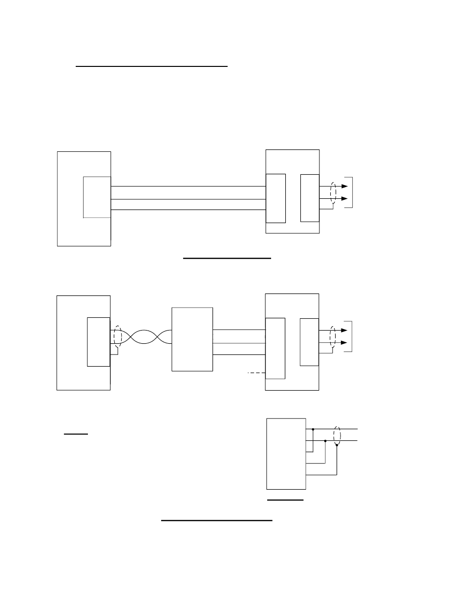
2.9 RS232 WIRING AT THE BMS II
The BMS II communicates with an external Energy Management System (EMS) or Building Automation
System (BAS) utilizing the wiring terminals labeled RXD (Receive Data), TXD (Transmit Data) and 232
ISO GND (Isolated Ground). If the EMS does not contain an RS232 port, a RS485-to-RS232 Converter
(AERCO Part No. 124943) is required to communicate with the BMS II. If a Converter is required, it can
be installed inside the wiring compartment of the BMS II, or installed externally. The BMS II provides an
isolated 12 VDC output terminal (ISO 12V) which can be used to power AERCO’s RS485-to-RS232
Converter if needed. Refer to Figure 2-12 for sample network layouts.
RS232
(50 FT. MAX.)
EMS
T+/R+
SHLD
RS
485
PORT
T-/R-
SEE NOTE 1
TO BOILERS
CONTROLLED
VIA RS485
NETWORK
(4000 FT. MAX.)
485
PORT
RXD
TXD
+(B)
-(A)
SHLD
BMS II
232
PORT
ISO
GND
+
-
TXD
RXD
GND
RS485-TO-RS232
CONVERTER
RS485
(4000 FT. MAX.)
ISO
12V
SEE
NOTE 2
T+
R-
R+
T-
SHIELD
4
-WIRE RS
485
PORT
DETAIL “A”
NOTES:
1. IF THE EMS CONTAINS A 4-WIRE RS485 PORT,
SEE DETAIL “A”.
2. THE BMS II PROVIDES A 12V OUTPUT IF
NEEDED TO POWER THE RS485-TO-RS232
CONVERTER.
RXD
TXD
+(B)
-(A)
SHLD
TO BOILERS
CONTROLLED
VIA RS485
NETWORK
(4000 FT. MAX.)
BMS II
485
PORT
RS232 (50 FT. MAX.)
EMS
TXD
GND
RS
232
PORT
RXD
232
PORT
ISO
GND
EMS WITH RS232 PORT
EMS WITH ONLY RS485 PORT
Figure 2-12. Sample Network Connections To EMS