Rs485 (modbus) wiring at the bms ii, Bms ii bias switches & loop termination resistors, Installation – AERCO BMS II BOILER User Manual
Page 20: 6 rs485 (modbus) wiring at the bms ii
INSTALLATION
2-8
2.6 RS485 (MODBUS) WIRING AT THE BMS II
The BMS II communicates with the AERCO Boilers over a RS485 network using Modbus protocol. All
Modbus networks are implemented utilizing a Master/Slave scenario where only one device, the Master,
can initiate a communication sequence. AERCO Boilers equipped with C-More or E8/BCM (Modulex)
control systems can only function as Slaves on a Modbus network. However, the BMS II can function as a
Master controlling C-More or E8/BCM Boiler Slaves, or as a Slave controlled by an Energy Management
System (EMS) developed by other manufacturers. Additional information on implementing Modbus
networks is provided in AERCO Modbus Communication Manual GF-114.
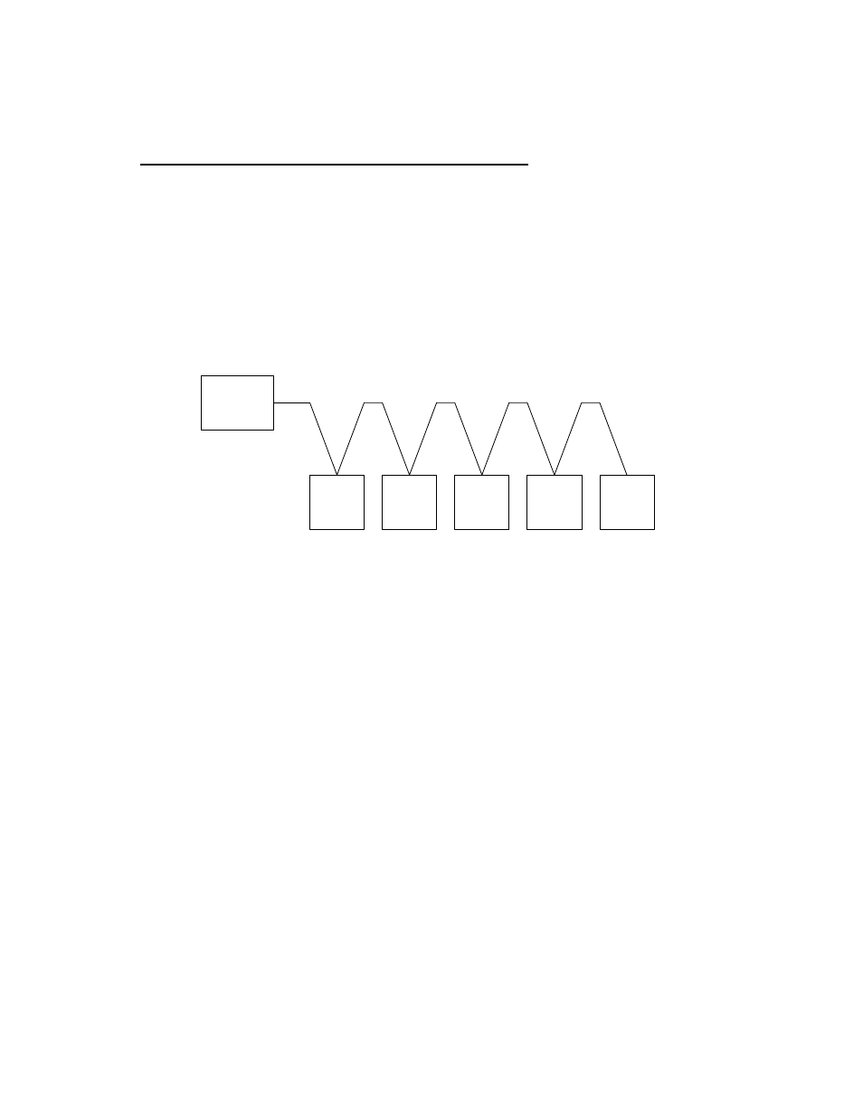
RS485 (Modbus) networks are wired in a “daisy chain” configuration similar to the example shown in
Figure 2-5. Shielded twisted-pair, 18 – 24 AWG cable (Belden #9841, #3105A, #8760 or equiv.) is
recommended for RS485 wiring connections.
MASTER
SLAVE
#1
SLAVE
#2
SLAVE
#3
SLAVE
#4
SLAVE
#5
Figure 2-5. Typical Daisy-Chain Modbus/RS485 Network
At the BMS II, RS485 (Modbus) wiring connections are made at the wiring terminals labeled 485 B+ and
485 A-. The cable shield is terminated at the SHLD terminal (3) of the BMS II.
BMS II Bias Switches & Loop Termination Resistors
Each BMS II contains a built-in 120 ohm loop termination resistor and two bias DIP switches which are
mounted on the lower portion of the motherboard (Figure 2-6). The 120 ohm termination resistor is always
active and is designed to match the electrical impedance at the BMS II end of the RS485 loop. Therefore,
only one additional termination resistor will be required at the boiler end of the RS485 loop. The two bias
switches are used to activate or deactivate bias voltage on the RS485 network and should be positioned
as follows, depending on the type of AERCO boilers being used:
NOTE
Refer to paragraph 2.7 for detailed instructions and illustrations
describing how to implement loop termination, bias and wiring connec-
tions on the RS485 loop.
1. When wiring to Boiler Control Modules (BCMs) controlling Modulex Boilers, the BMS II bias switches
must be activated by placing them in the on (down) position. Loop termination is accomplished by
activating the termination resistor in the last BCM on the RS485 loop.
2. When wiring to C-More control systems (Benchmark & KC1000 Boilers), the positions of the BMS II
bias switches will depend on which one of the two available methods is used. Loop termination will
also depend on the method employed. See paragraph 2.7 for details.