Rs485 wiring for modulex series boilers, Sample rs485 (modbus) network diagrams, Installation – AERCO BMS II BOILER User Manual
Page 27: 8 sample rs485 (modbus) network diagrams, Bcm front view
INSTALLATION
2-15
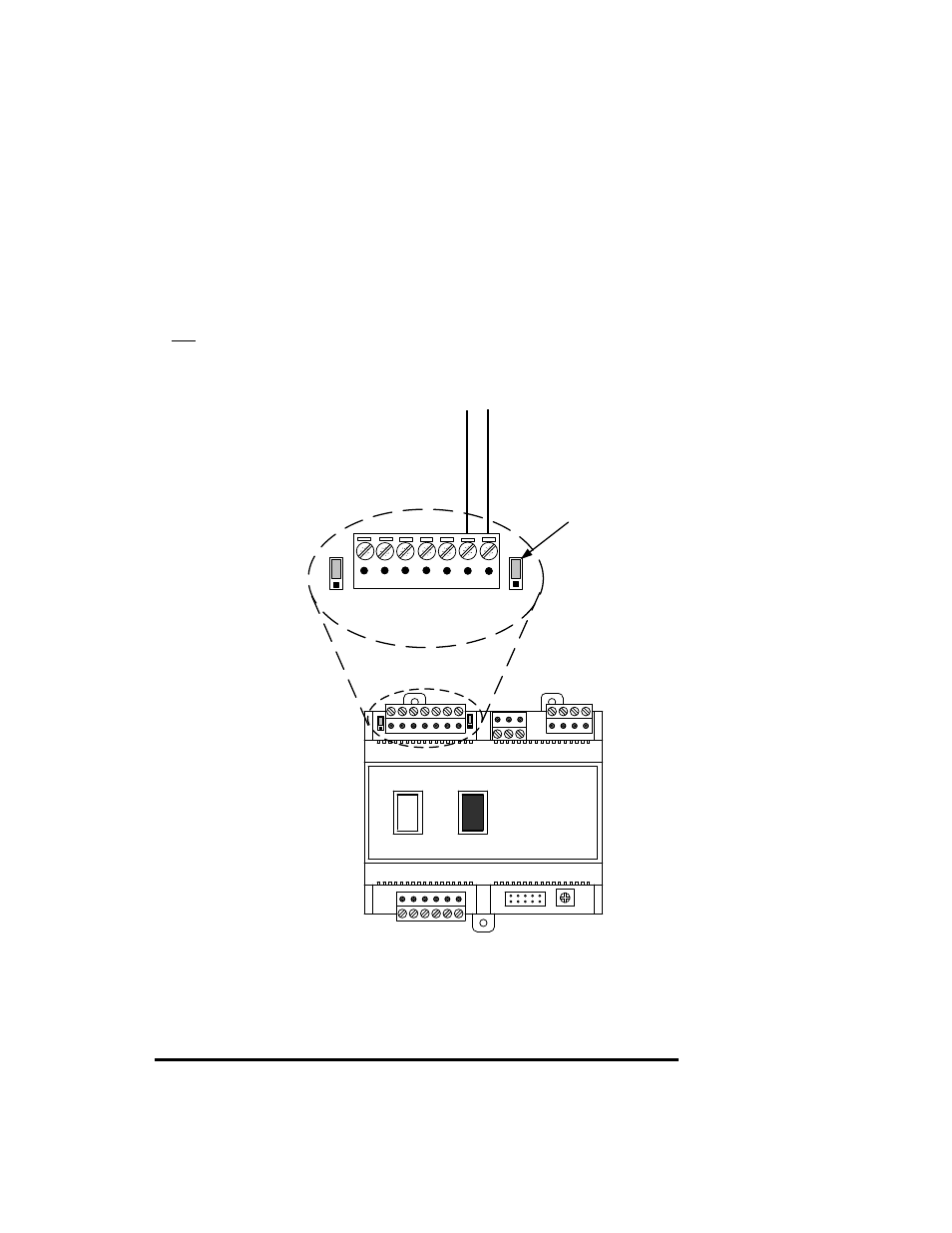
RS485 Wiring for Modulex Series Boilers
RS485 wiring connections are made at the MODBUS terminals of each Boiler’s BCM Module as shown in
Figure 2-9. Connect the wiring as follows:
1. Connect the positive lead to terminal 1 (MODBUS B +) of connector Y2.
2. Connect the negative lead to terminal 2 (MODBUS A -) of connector Y2.
3. DO NOT terminate the shields at the Boiler end of the RS485 loop. Connect the shields of the
incoming and outgoing leads together. The RS485 loop shield should only be terminated at the BMS
II.
4. The last BCM in the daisy-chain must have the termination jumper engaged as shown in Figure 2-9.
5. The two BMS II bias switches (Figure 2-6) must be activated by placing them in the down position.
Y2
Y3
Y4
Y1
SW1
A1
I
0
BCM FRONT VIEW
7 6 5 4 3 2 1
Y2
JP2
JP1
T
C
V
JUMPER
SHOWN IN
“TERMINATED”
(UP) POSITION
MODBUS B
(+)
MODBUS A
(-
)
Figure 2-9. RS485 (Modbus) Wiring For Modulex Series Boilers
2.8 SAMPLE RS485 (MODBUS) NETWORK DIAGRAMS
Figure 2-10 shows a sample RS485 (Modbus) Network diagram with the BMS II connected to KC1000 or
Benchmark Series Boilers equipped with C-More Control Systems. Figure 2-11 shows a similar sample
diagram with the BMS II connected to Modulex Series Boilers equipped with BCMs and E8 Controllers.