7 troubleshooting, English, English 7 troubleshooting – KEYENCE SL-R11E User Manual
Page 42: Chapter 7 troubleshooting
Chapter 7 Troubleshooting
7-2
7
English
ENGLISH
7 Troubleshooting
When either the Safety Light Curtain SL-C Series or the Safety Control Unit
SL-R11E experiences an error, it is possible to determine the cause of the
error by referring to the state of the bar LED display on the SL-C.
When the lock-out indicator (orange) is flashing, the device can be returned
to normal operation by turning it off and then on again once the cause of the
problem has been rectified.
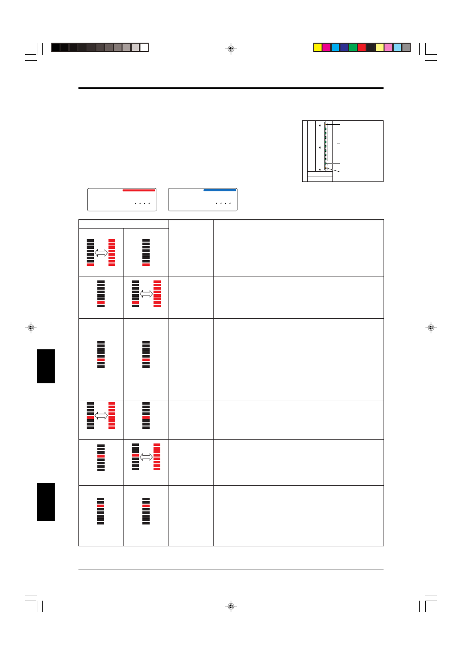
The following stickers have been affixed to transmitters and receivers. Verify
the on/off status of the LED after checking the orientation of the system's
transmitters and receivers.
Transmitter
Receiver
SL-C08H-T
RATED VOLTAGE / CURRENT
TYPE OF POWER SUPPLY
RESPONSE TIME
DETECTION ZONE (PROTECTION ZONE)
DETECTION CAPABILITY
EAA
ENCLOSURE RATING
AMBIENT TEMPERATURE
Transmitter
24V DC 55mA Class2
See Instruction Manual
15ms
140mm(185mm)
φ 25/ φ 45/ φ 65/ φ 85mm
± 2.5˚ (3m or more)
IP65
-10˚C to 55˚C
SL-C08H-R
RATED VOLTAGE / CURRENT
TYPE OF POWER SUPPLY
RESPONSE TIME
DETECTION ZONE (PROTECTION ZONE)
DETECTION CAPABILITY
EAA
ENCLOSURE RATING
AMBIENT TEMPERATURE
Receiver
24V DC 67mA Class2
See Instruction Manual
15ms
140mm(185mm)
φ 25/ φ 45/ φ 65/ φ 85mm
± 2.5˚ (3m or more)
IP65
-10˚C to 55˚C
Bar LED display status
Receiver
Description
Causes and solutions
Transmitter
1 and all lamps
alternately light up
1 lights up
Transmitter error
2 lights up
Receiver error
3 lights up
3 lights up
SL-R11E error
• Reconnect the SL-R11E and SL-C connectors as described in section 4-1
“Method for Connection to the SL-C Series” (
➮4-1) in the SL-R11E manual.
• The wrong cable is being used to connect the SL-R11E and SL-C. Use the
correct type of cable as described 4-1 “Method for Connection to the SL-C
Series” (
➮4-1) in the SL-R11E manual.
• The SL-R11E mode switch has not been set properly. Follow the instructions in
section 2-11 "Mode switch setting (
➮2-5)" of this manual to set the switch properly.
• The short bar attached when shipped from the factory is detached or loose.
Attach the short bar according to the function setting to be used. If it is already
attached, tighten the screws on the terminal block.
• If the MPCE monitor function is being used, the MPCE is damaged or has not
been wired properly. Check the MPCE and its wiring as described in section 4-
3-3 “Wiring to the MPCE Monitor Input Terminal” (
➮4-7) in the SL-R11E
manual.
• The SL-R11E is damaged and needs to be replaced.
4 lights up
Inconsistent
number of
transmitter and
receiver beam
axes
• Different models of transmitter and receiver are being used so that the number of
beam axes does not match. Use a proper combination of models.
• If being connected in series, use the same model and number of connected SL-C
units on both the transmitter and receiver sides of the system.
5 lights up
Light interference
Interfering
light received
• The receiver is receiving light that originated in an SL-C transmitter that is not
its matched pair. Fix this problem as described in either section 2-3-5 “Light
Interference Prevention Method” (
➮2-12) in the SL-C manual or section 4-4
“About the Light Interference Prevention Connection” in the SL-R11E manual
(
➮4-10).
• The receiver is receiving light originating from an inverter fluorescent light or
another sensor. Prevent this light from entering the receiver by adjusting the
location at which the sensor is installed or installing a masking plate.
6 lights up
6 lights up
Communications
error
• Reconnect the SL-R11E to the SL-C as described in section 4-1 “Method for
Connection to the SL-C Series” (
➮4-1) in the SL-R11E manual.
• If light interference prevention connections have been made, the main/sub switch
is set so that there are multiple mains configured. Always configure the system
so that there is only 1 main, as described in section 4-3-4 “Connecting to
Main/Sub Select Input Terminal” (
➮4-8) in the SL-R11E manual.
• If the unit has been configured as a sub with the light interference prevention
connection, the power has been cut to the sensor that is configured for either the
main or the sub that is connected closer to the main. Be careful not to cut power
to only some of the connected sensors.
2 and all lamps
alternately flash
4 and all lamps
alternately light up
5 and all lamps
alternately light up
• Reconnect the receiver and cable as described in section 2-3-1 “Connecting
Cable Installation” (
➮2-7 ) in the SL-C manual.
• Reconnect the SL-R11E and receiver connectors as described in section 4-1
“Method for Connection to the SL-C Series” (
➮4-1) in the SL-R11E manual.
• The receiver is damaged. Replace the sensor.
• Remove any extension cable from the transmitter side (Receiver Side).
• Remove any series connection heads and retest with only the first set of heads.
• Reconnect the transmitter and cable as described in section 2-3-1 “Connecting
Cable Installation” (
➮2-7) in the SL-C manual.
• Reconnect the SL-R11E and transmitter connectors as described in section 4-1
“Method for Connection to the SL-C Series” (
➮4-1) in the SL-R11E manual.
• The transmitter is damaged. Replace the sensor.
• Remove any extension cable from the transmitter side (Receiver Side).
• Remove any series connection heads and retest with only the first set of heads.
8
7
6
5
4
3
2
1
LOCKOUT
ON/OFF
FUNCTION
1. Lockout indicator
4. Function indicator
2. Bar LED
3. Output
status indicator
7-1